


What is Time-of-Flight sensors|| These are versatile devices with a diverse set of capabilities such as object detection, depth estimation, and object classification. Specific applications include inventory management/counting, people tracking, and parking monitoring. In addition to these useful but seemingly mundane applications, Time-of-Flight sensors (ToF) sensors can be integrated and expanded into more unique applications.
One of these exciting applications is a smart automatic secret door. Imagine the hero in a spy movie trying to open a secret door by standing in a hallway next to a non-descript vase while making a series of gestures. Suddenly, a door opens to a hidden room full of secret intel. Using only a single ToF sensor, the smart automatic secret door remains secure by allowing entrance only to people who know where to stand (a specific part of the room) and know to perform secret gestures (multiple if needed). Another application for ToF sensors is posture or technique monitoring in sports. For example, a ToF sensor can help perfect a golfer’s technique by monitoring his pose.
How do we integrate a Time-of-Flight sensor, and what is needed for these exciting applications? Read on to understand how ToF sensors work and how they can be integrated into a given application, as well as what to consider when using ToF sensors.
What is Time-of-Flight Sensor: Basics
As the name suggests, Time-of-Flight sensors use the time for light (generally infrared, ~850nm) or emitted sound (ultrasonic) to “fly” to and reflect off objects to measure distance. The principle of how these sensors work is extremely simple. For further simplicity, optical ToF sensors will be our sole focus.
ToF sensors can be divided into two categories based on how they measure distance: Direct and indirect. Direct ToF sensors directly measure the time for a given pulse of light to be transmitted by the sensor, reflected off the object of interest, and received at the detector. Direct ToF sensors typically send out pulsed modulations to measure distance. For a direct ToF sensor, distance is measured by the following equation:
d = (c ⋅ Δt) / 2
Where Δt is the time difference,
and c is the speed of light.
Indirect ToF sensors, on the other hand, measure the relative phase differences between pulses. Thus, over a series of pulses transmitted by the sensor, reflected off the object of interest, and received at the detector, the distance can be measured by looking at the difference in phase of the returned signal to the transmitted signal. Indirect ToF sensors generally send out continuous wave (CW) modulations to measure distance. For an indirect ToF sensor, distance is measured by the following equation:
d = (c / 2ƒm) ⋅ (Δθ / 2π)
Where Δθ is the phase difference,
ƒm is the modulation frequency,
and c is the speed of light.
Differences between direct and indirect ToF sensors are summarized in Table 1, although exceptions to some of the criteria exist.
Table 1: ToF sensor types: Indirect and direct measurement (Source: Author)
| Indirect ToF Sensor | Direct ToF Sensor |
| 🗶 Aliasing (ambiguity) | ✔ No aliasing (no ambiguity) |
| 🗶 Slower integration (multiple samples) | ✔ Faster acquisition |
| ✔ Higher pixel count | 🗶 Lower pixel count |
| ✔ Lower transmitted peak power (CW) | 🗶 Higher transmitted peak power |
| 🗶 Lower range (depends on modulation frequency) | ✔ Higher range |
| ✔ Lower data volume | 🗶 Higher data volume |
Indirect ToF sensors are more suitable for 3D applications such as gesture recognition, while direct ToF sensors are more suitable for fast ranging based. The suitability of these sensors for specific applications is based on operating principles. Understanding how ToF sensors work helps to choose the correct sensor for the application.
Life of a Photon for a ToF Sensor
The operating conditions and environment are key to understanding how ToF sensors work. Figure 1 shows the “life” of photons for a ToF sensor and notionally where noise can occur. Red indicates places where noise can occur and/or affect how the system ultimately performs. At the receiver, only a small fraction of the transmitted photons will ever be collected due to the probability of photons going through this chain of events “properly.”

Figure 1: This diagram shows how a photon interacts for a ToF sensor. (Source: Author)
Photon Scattering and Interactions
The interaction of the transmitted signal (photons) with the object of interest is extremely important for ToF sensors as photons can have diffuse reflections, specular reflections, and/or spread reflections, and be absorbed or scattered based on the object (Figure 2). For example, if the object that is being measured has a rough surface (irregular lattice arrangements) and is on the scale of a wavelength, diffuse scattering will be the dominant interaction. How photons interact with the object will affect how well a ToF sensor will work in practice.
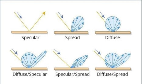
Figure 2: Light can scatter in several different ways when interacting with objects. (Source: Terabee)
ToF Comparison with 3D Optical Sensing Systems
ToF sensors can be compared to two other 3D optical sensing systems: Structured light sensors and stereo vision systems. No “best sensor” exists: Table 2 and Table 3 highlight the pros and cons of ToF sensors.
Table 2: High-level pros of ToF sensors (Source: Author)
| Pros of ToF Sensors |
| Compact size and easy to use |
| High accuracy and fast response |
| Good spatial resolution |
Table 3: Things to consider when using ToF sensors (Source: Author)
| Cons of ToF Sensors |
| Artifacts can be present (motion blur) |
| Calibration can be difficult |
| Robust to ambient light, but can degrade fast |
ToF sensors clearly have some advantages over 3D optical sensing systems, but a design engineer should consider all possibilities when making a decision. Table 4 highlights the advantages and disadvantages of 3D optical sensing systems in direct comparison to ToF sensors (again, note that exceptions exist).
Table 4: Full comparison of ToF sensors with other 3D sensing optical systems (Source: Author)
| Stereo Vision | Structured Light | ToF | |
| Range | < 10 meters | < 5 meters | < 50 meters |
| Cost | Medium | High | Low |
| Spatial Resolution | High | High | Medium |
| Complexity | High | High | Low |
| Depth Accuracy | Low | High | Medium |
| Low Light Performance | Low | High | High |
| High Ambient Light Performance | Medium | Low | Medium |
| Size | Medium | Medium | Low |
| Artifacts | High | Low | High |
| Field of View | < 90 degrees | < 90 degrees | Varies |
| Power | Low | Medium | Medium |
ToF Sensor Integration Considerations and Errors
Integrating ToF sensors can be relatively straightforward (at a hobby level) since most ToF sensors contain everything needed (emitter, receiver, and processor) in a single package. Care must be taken, however, depending on the application and use. Many different configurations for ToF sensors exist, including emitter designs, receiver designs, and/or operational features (e.g., steered, rotating). Design and manufacture of each ToF sensor plays an extremely important role in how the sensor will perform and the capabilities that the sensor can achieve.
One key consideration for integrating a ToF sensor into an application is the calibration process. Four types of errors seen by ToF sensors when measuring range at the most simplistic level are shown in Figure 3: Constant offset, scale factor, measurement accuracy/variance, and saturation. Moving forward, our focus will be on a single emitter and single receiver (pixel).

Figure 3: The errors that appear when using a ToF sensor are depicted. (Source: Author)
ToF Errors and Noise Deep Dive
In engineering and scientific applications, understanding and calibrating out the sources of error is essential. First, because ToF sensors are optical sensors, noise sources in optical sensors are present in ToF sensors. We must consider fixed pattern noise and deviations in pixel response from one pixel to the next within the ToF sensor’s focal plane array (FPA). Responsivity of each pixel in the array must be compensated to a uniform level. Another type of fixed pattern noise is dark current and its corresponding shot noise. Even when the ToF sensor is not illuminated, noise will still be present in the sensor. This must be compensated to reduce offsets in the readout of the FPA. In general, the bandgap of the sensor is inversely proportional to the dark current noise. As the bandgap decreases, dark current noise typically increases.
To compensate for fixed pattern noise, a process called nonuniformity correction (NUC) can be performed. This process includes measuring the array at different integration times and fitting the response to a known model. Each pixel must be corrected and aligned to give a uniform output for a fixed input. To give an example (although not for a ToF sensor), if a NUC is performed properly, the results will look something like those in Figure 4.

Figure 4: This image displays an example of a NUC process in correcting infrared sensors. For 3D sensing applications, a calibration process will be necessary to achieve good results. (Source: https://sites.google.com/a/udayton.edu/rhardie1/research/nonuniformity-correction)
Other system noise that must be accounted for includes thermal noise, quantization noise (analog-to-digital converter), flicker noise, kTC noise, and crosstalk. Thermal noise in particular should be considered because the response of a detector is also affected by temperature. Ranging will drift as a function of temperature and will present itself as an offset. This drift in temperature is not a function of the object; causes for this thermal drift relate to the phase measurements of the delay-locked loop.
Environmental noise that will affect the ToF sensor’s performance includes stray light, optical wavefront error, multipath, and general illumination noise due to uneven object reflectivity. As noted above in the discussion of cons for the use of ToF sensors, ToF sensors suffer from artifacts that should be corrected, such as motion artifacts. Motion artifacts occur at object boundaries and inhomogeneous reflections where unmatched raw phase values can fluctuate. As the motion speed increases for a given integration time, the motion artifacts become more severe. To compensate for motion artifacts, several techniques can be employed including flow compensation. This compensation must be run as the sensor is running and cannot be treated as a calibration.
ToF Sensor Example
With this understanding of ToF sensors, we can review, at a high level, how to use a ToF sensor for object tracking.
Using a ToF sensor, a point cloud is first generated by measuring the range of many points of an object or scene. Depending on the density of the ToF sensor returns/point cloud and the accuracy of the range measurements, an accurate 3D view of the sensor and the world it sees can be made. If the view of the sensor is empty except for a single object, the object can simply be tracked by looking at returns that are at a different range from the rest of the scene. On the other hand, if the scene is cluttered, applying some image processing allows objects to be tracked based on object feature with the additional information of depth. A proper ToF sensor provides a camera-like “image,” but with additional depth information.
The resolution of the ToF sensor is critical—similar to when resolution is too low with a camera and an accurate point cloud cannot be made. If the range is not representative and the ToF sensor is not calibrated, objects will bleed into each other, or flat surfaces such as a wall will look rough and distorted.
Conclusion
ToF sensors are versatile and, if examined carefully, have an incredible amount of depth. Use and design of ToF sensors vary due to the types of emitters, detectors, optical array, processing, and general packaging. Noise and errors of ToF sensors should be accounted for in any application; depending on what the sensor will be used for, the calibration and error correction could become complicated. Ultimately, ToF sensors are compact, have amazing performance, and, given the capabilities, are cost-effective solutions to many different problems.
The blog has been first published on Mouser Electronics.


