


Abstract
Lithium-ion batteries are a popular way to store energy in electric and hybrid vehicles. These batteries offer the highest energy density of any current battery technology, but to maximize performance, a battery monitoring system (BMS) is mandatory. A state-of-the-art BMS not only allows you to extract the highest quantity of charge from your battery pack, but also lets you manage the charge and discharge cycles in a safer way, which results in an extended life. Analog Devices provides a full portfolio of BMS devices with focus on accuracy and robust operation.
Accurately measuring a battery’s state of charge (SOC) increases battery run time or decreases weight. A precise and stable device does not require factory calibration after PCB assembly. Stability over time improves safety and avoids warranty problems. A self-diagnostics feature helps reach the right automotive safety integrity level (ASIL). A battery pack is a challenging environment for electromagnetic interferences (EMI), so special care has been put into designing the data communication link in order to ensure robust and reliable communication between the measurement chips and the system controller. Cables and connectors are among the main causes of failures in battery systems, so wireless solutions are presented here. Wireless communication designs increase reliability and reduce total system weight, which in turn increases mileage per charge.
Introduction
An energy storage unit has to provide high capacity and the ability to release the energy in a controlled manner. Storage and release of energy, if not properly controlled, can result in a catastrophic failure of the battery and ultimately fire. Batteries can fail for several reasons, most of them related to inappropriate use. Failure can come from mechanical stress or damage, electrical overstress in the forms of deep discharge, overcharging, overcurrent, and thermal overstress. In order to reach the highest levels of efficiency and safety, a battery monitoring system is required.
The main function of the BMS is to keep any single cell of the battery pack inside its safe operating area (SOA) by monitoring the following physical quantities: stack charge and discharge current, single cell voltage, and battery pack temperature. Based on these quantities, not only can the battery be operated safely, but also SOC and state of health (SOH) can be computed.
Another important feature provided by the BMS is cell balancing. In a battery stack, single cells can be arranged in parallel and in series in order to achieve the required capacity and operating voltage (up to 1 kV or higher). Battery manufacturers attempt to provide stacks with identical cells, but this is not physically possible. Even small differences lead to different charge or discharge levels, with the weakest cell in the stack disproportionately affecting overall stack performance. Accurate cell balancing is a significant feature in a BMS, enabling safe operation of a battery system at its highest capacity.
BMS Architectures
An electric vehicle battery consists of several cells stacked in series. A typical stack—with 96 cells in series—when charged at 4.2 V can develop a total voltage in excess of 400 V. Higher voltages can be reached by stacking more cells. Charge and discharge current are the same for all the cells, but voltages have to be monitored on every single cell. To accommodate the large quantity of cells required for high powered automotive systems, batteries are often divided into modules, and distributed throughout available spaces in the vehicle. With 10 cells to 24 cells in a typical module, modules can be assembled in different configurations to suit multiple vehicle platforms. A modular design can be used as the basis for very large battery stacks. It allows battery packs to be distributed over larger areas for more effective use of space.
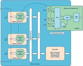
Analog Devices has developed a family of battery monitors capable of measuring up to 18 series connected cells. The AD7284 can measure 8 cells, the LTC6811 can measure 12 cells, and the LTC6813 can measure 18 cells. Figure 1 shows a typical battery pack with 96 cells, divided into 8 modules of 12 cells each. In this case, the battery monitor IC is the 12-cell LTC6811. The cell measurement range is 0 V to 5 V, making the IC suitable for most battery chemistries. Multiple devices can be connected in series, permitting simultaneous cell monitoring of long, high voltage battery stacks. The device includes passive balancing for each cell. Data are exchanged across an isolation barrier and compiled by the system controller, which is in charge of computing the SOC, controls cell balancing, checks the SOH, and maintains the full system inside the safety constraints.
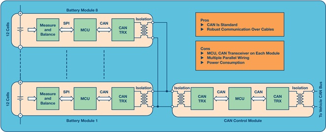
To support a distributed, modular topology within the high EMI environment of an EV/HEV, a robust communication system is required. Both isolated CAN bus and ADI’s isoSPI™ offer road-proven solutions for interconnecting modules in this environment.1 While the CAN bus provides a well-established network for interconnecting battery modules in automotive applications, it requires a number of additional components. For example, implementing an isolated CAN bus via an LTC6811’s isoSPI interface requires the addition of a CAN transceiver, a microprocessor, and an isolator. The primary downside of a CAN bus is the added cost and board space required for these additional elements. Figure 2 shows a possible architecture based on CAN. In this case, all modules are parallel connected.
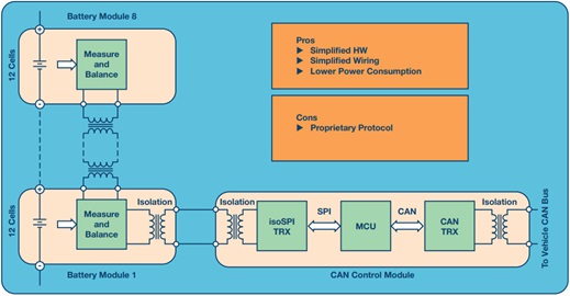
An alternative to a CAN bus interface is ADI’s innovative 2-wire isoSPI interface.1 Integrated into every LTC6811, the isoSPI interface uses a simple transformer and a single twisted pair, as opposed to the four wires required by the CAN bus. The isoSPI interface provides a noise-immune interface (for high RF signals) in which modules can be connected in a daisy-chain over long cable lengths and operated at data rates up to 1 Mbps. Figure 3 shows the architecture based on isoSPI and using a CAN module as a gateway.
There are pros and cons to the two architectures presented in Figure 2 and Figure 3. CAN modules are standard and can be operated with other CAN subsystems sharing the same bus; the isoSPI interface is proprietary and communication can happen only with devices of the same type. On the other hand, the isoSPI modules do not require an additional transceiver and the MCU to handle the software stack, resulting in a more compact and easy-to-use solution. Both architectures require a wired connection, which has significant disadvantages in a modern BMS, where routing wires to disparate modules can be an intractable problem, while adding significant weight and complexity. Wires are also prone to pick up noise, leading to the requirement for additional filtering.
Wireless BMS
The wireless BMS is a novel architecture that removes the communication wiring.1 In a wireless BMS, each module is interconnected via a wireless connection. The biggest advantages of a wireless connection for large multicell battery stacks are:
- Reduced wiring complexity
- Less weight
- Lower cost
- Improved safety and reliability
Wireless communication is a challenge due to the harsh EMI environment, and the RF shielding metal posing as obstacles to signal propagation.
ADI’s SmartMesh® embedded wireless network, field-proven in industrial Internet of Things (IoT) applications, delivers >99.999% reliable connectivity in industrial, automotive, and other harsh environments by employing redundancy through path and frequency diversity.
In addition to improving reliability by creating multiple points of redundant connectivity, the wireless mesh network expands BMS capability. The SmartMesh wireless network enables flexible placement of battery modules and improves battery SOC and SOH calculations. This is because additional data can be gathered from sensors installed in locations otherwise inhospitable to a wiring harness. SmartMesh also enables time-correlated measurements from each node, allowing for more precise data collection. Figure 4 shows a comparison of wired- and wireless-interconnected battery modules.

ADI is demonstrating the industry’s first wireless automotive BMS concept car, combining the LTC6811 battery stack monitor with ADI’s SmartMesh network technology in a BMW i3.2 This is a significant breakthrough that has the potential to improve reliability and reduce cost, weight, and wiring complexity for large multicell battery stacks for EV/HEV.
The Importance of an Accurate Measurement
Accuracy is an important feature for a BMS and it is critical for LiFePO4 batteries.3,4 To understand the importance of this feature, let’s consider the example in Figure 5. To prevent overcharge and discharge, the cells of the battery are kept between 10% and 90% of full capacity. In a 85 kWh battery, only 67.4 kWh are available for normal driving. If there is a measurement error of 5%, to continue to operate the battery safely, the cells must be kept between 15% and 85% of their capacity. The total available capacity has been reduced from 80% to 70%. If accuracy is improved to 1% (for LiFePO4 batteries 1 mV measurement error translates into 1% SOC error), the battery can be operated now between 11% and 89% of full capacity, with a gain of 8%. With the same battery and a more accurate BMS, automobile mileage per charge is increased.

Circuit designers rely on data sheet specifications to estimate the accuracy of a cell measurement circuit. Other real-world effects often dominate the measurement error. Factors affecting the measurement accuracy are:
- Initial tolerance
- Temperature drift
- Long-term drift
- Humidity
- PCB assembly stress
- Noise rejection
A good technology must take into account all of these factors in order to deliver very high performance. Measurement accuracy of the IC is primarily limited by the voltage reference. Voltage references are sensitive to the mechanical stress. Thermal cycling during PCB soldering stresses silicon. Humidity is another cause of silicon stress as water is absorbed in the package. Silicon stress relaxes over time, leading to long term drift of the voltage reference.
Battery measurement ICs use either a band gap voltage reference or a Zener voltage reference. IC designers use an NPN emitter-base junction operating in reverse breakdown as a Zener reference. Breakdown occurs at the surface of the die, where the effects of contamination and oxide charge are most pronounced. These junctions are noisy and suffer from unpredictable short- and long-term drift. The buried Zener places the junction below the surface of the silicon, well away from contamination and oxide effects. The result is a Zener with excellent long-term stability, low noise, and relatively accurate initial tolerance. For that reason, Zener references are far superior for mitigating real world effects over time.
The LTC68xx family uses a laboratory grade Zener reference, a technology ADI has perfected over 30 years. Figure 6 shows the drift over temperature of the battery measurement IC error for five typical units. The drift in the full automotive range of –40°C to +125°C is less than 1 mV.

Figure 7 shows a comparison of the long-term drift for a bandgap voltage reference IC and a buried Zener voltage reference IC. The initial measurements are calibrated for 0 mV of error. Ten years of measurement drift is predicted from drift after 3000 h at 30°C. The picture clearly shows a much better stability of the Zener reference over time, at least 5× better than bandgap reference. Similar tests for humidity and PCB assembly stress show the superior performance of the buried Zener over the band gap voltage reference.

Another limiting factor for accuracy is noise. A car battery is a very harsh environment for electronics due to the electromagnetic interference generated by the electric motor, the power inverter, the dc-to-dc converters, and other high current switching systems in an EV/HEV. The BMS should provide a high level of noise rejection in order to maintain accuracy. Filtering is the classical method used to reduce unwanted noise, but there is a trade-off between noise reduction and speed of conversion. Due to the high number of cell voltages to be converted and transmitted, the conversion time can’t be too slow. SAR converters might be the preferred choice, but in a multiplexed system, speed is limited by the settling time of the multiplexed signal. In this case, sigma-delta (Σ-Δ) converters can be a valid alternative.
The ADI measurement ICs use sigma-delta analog-to-digital converters (ADCs). With a sigma-delta converter, the input is sampled many times during a conversion, and then averaged. The result is built-in low-pass filtering to eliminate noise as a source of measurement error; the cutoff frequency is established by the sample rate. The LTC6811 uses a third-order sigma-delta ADC with programmable sample rates and eight selectable cutoff frequencies. Figure 8 shows the filter response for the eight programmable cutoff frequencies. Outstanding noise reduction is achieved by enabling measurement of all 12 battery cells as fast as 290 µs. A bulk current injection test, where 100 mA of RF noise is coupled into the wires connecting the battery to the IC, showed less than 3 mV of measurement error.

Cell Balancing for Optimized Battery Capacity
Battery cells, even if accurately manufactured and selected, show slight differences from each other. Any mismatch in capacity between the cells results in a reduction of the overall pack capacity.
To better understand this point, let’s consider our example where the cells were kept between 10% and 90% of the full capacity. The effective lifetime of a battery can be significantly shortened by deep discharge or overcharging. Therefore, the BMS provides undervoltage protection (UVP) and overvoltage protection (OVP) circuitry to help prevent these conditions. The charging process is stopped when the lowest capacity cell reaches the OVP threshold. In this case, the other cells are not fully charged and the battery is not storing the maximum allowed energy. Similarly, the system is stopped when the lowest charged cell hits the UVP limit. Also, there is still energy in the battery to power the system, but, for safety reasons, it can’t be used.
It is clear that the weakest cell in the stack dominates the performances of the full battery. Cell balancing is a technique that helps overcome this issue by equalizing the voltage and SOC among the cells when they are at full charge.5 There are two techniques for cell balancing—passive and active.
With passive balancing, if one cell becomes overcharged, the excess charge is dissipated into a resistor. Typically, there is a shunt circuit which consists of a resistor and a power MOSFET used as a switch. When the cell is overcharged the MOSFET is closed and the excess energy is dissipated into the resistor. The LTC6811 balances each monitored cell using an internal MOSFET to control the individual cell charge currents. The internal MOSFETs enable compact designs, and suffice for currents to 60 mA. For higher charge currents, external MOSFETs can be used. Timers are also provided to adjust the balancing time.
Advantages of the dissipative technique are low cost and low complexity. Disadvantages are high energy loss and a more complex thermal design. Active balancing, on the other hand, redistributes the excess energy between the other cells of the module. This way the energy is recovered and less heat is generated. The disadvantage of such a technique is a more complex hardware design.
Figure 9 shows an active balancing implementation using the LT8584. This architecture solves the problems of passive shunting balancers by actively shunting the charging current and returning the energy back to the battery stack. Instead of the energy being lost as heat, it is reused to charge the rest of the batteries in the stack. The architecture of the device also solves the problem of reduced run time when one or more of the cells in the stack reaches the lower safety voltage threshold before the entire stack capacity is extracted. Only active balancing can redistribute the charge from the stronger cells to the weaker cells. This allows the weaker cells to continue to supply the load, extracting the highest percentage of energy from the battery. The flyback topology allows the charge to return between any two points in the battery stack. Most applications return the charge to the module cells (12 or more), others return the charge to the entire battery stack, and some applications return the charge to an auxiliary power rail.

Conclusion
Electrification is the key for lower emission vehicles, but requires a smart management of the energy source—the Li-Ion battery. If not managed properly, a battery pack can become unreliable, and drastically reduce the safety of the automobile. High accuracy helps maximize the performance and the life of the battery. Active and passive cell balancing allow a safe and efficient battery management. Distributed battery modules are easily supported, and a robust communication of the data to the BMS controller, both wired and wireless, allows reliable SOC and SOH calculations.


