


Many people often surf on the internet about making a LED bulb, but their search ends on how to just conduct assembly of the bulb, no one says about its driver circuit design and PCB. Whereas, if you buy it’s all the elements from a good dealer or buys it online, then chances of savings in the business reduce. The solution is you should at least design its driver circuit plate, than you can save your money. So let’s start with “How to make LED Bulb in Hindi with circuit”.
Material for making LED bulb
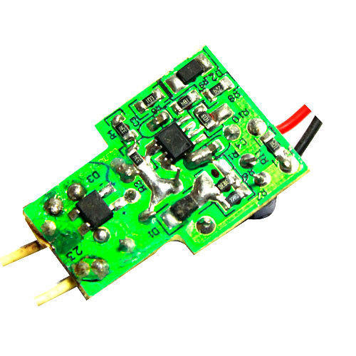
1). LED Driver circuit (Pcb board)
2). LED Board (with LED mount)
3). Aluminum Heat sink plate
4). Plastic Housing
5). Metal cap
You can also get all raw materials of LED bulb online or by contacting a dealer directly. If you take stuff together in a bulk, then it will be very cheap. In order to make more profit in LED bulb business, I would suggest that at least you can make driver circuit PCB by itself, which is the most expensive part, it will make your business more profitable.
LED Driver circuit
Here, 24 LEDs are shown in the circuits, in which high bright white LED (50mA) has been used. Input mains is 220VAC in which the bridge rectifier is made to convert AC from 4 diodes to DC and after which the capacitor is applied to remove AC pulses. After that, 24 LEDs have been added to the series. Here, kindly find the list of components separately.
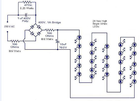
1). 470 ohm 0.25W Resistor (01 nos.)
2). 100 ohm 0.5W (02 nos.)
3). 1uF 400V (01 nos.)
4). 10uF 16.0V (01 nos.)
5). LEDs 50mA (24 nos.)
If the LED bulb made of this circuit is compared to 11-watt tube light, then the brightness of the LED bulb is much better. This is the only part of the LED bulb business, that you can either design if you know about electronics software or you can get it designed from an engineer. You can also download free software from the internet.
Assemble PCB components:
When you get a PCB design, it comes with a software file that you should keep safe and whenever you want to create a PCB plate, you can easily create it by accessing that file. The PCB is the only designed once, then the same file is always used. If you build plate in more quantity then it will be cheaper.
Now buy all its components from the market and start soldering on PCB. Keep track of + and – for capacitor and diode. After mounting all the components, separate the wire solder on the input and output so that the mains with 220V and LEDs are connected.
Mount the LED board on aluminum heatsink:

When the LED burns with full brightness, it generates heat which causes its early degradation, so heat sink is used to reduce the heat. For the LED bulb, its board size aluminum heatsink will be available only with the board. To paste the LED board on it, you have to buy the heat sink compound from the market and first put the compound on the heatsink and then place LED board up and paste.
Mount the LED driver in Housing:
Fix the LED driver PCB by putting it inside the housing, keep in mind that PCB does not move. To fix, you can stick to the hot gun by applying glue.
Add the input wire to the metal cup of the Driver circuit:
 Now remove both the wires of the LED driver’s input mains 220V from the metal cup holes and solder them well, be careful that the solder is not dry.
Crimp metal cup with housing:
Now join the metal cup with the housing, press the crimping machine, so that the two will be well connected together. Just remember, that both should be properly fixed and not shaken.
Solder LED board with driver PCB:
From now onwards, start soldering by connecting both pins of the driver PCB output to the LED board.
Mount the LED board above the housing:
In the housing, there are some locking systems for fixing the LED board, so that the board should be well trapped and does not move.
Fit the plastic cup above the housing:
Now put the plastic cup that comes with the bulb and close the bulb with it. Now you can test your bulb by putting it on the board of the mains supply, if the bulb is burning well then you are successful.


 Validation Solution for AI Networks")
