


Modern power and garden tools, vacuum cleaners and other end equipment are getting smarter with wireless connectivity. Wireless connectivity offers features such as authentication, tracking, intelligent inventory management, immediate fault reporting, and status about battery condition and total operating duration. Wireless connectivity also enables online configuration of control parameters and firmware updates.
The most common solution for wireless connectivity in end equipment like power tools, garden tools and vacuum cleaners is a Bluetooth® low energy module, either assembled inside the equipment or provided as a separate unit attached to the product. The existing architecture of these products uses one independent microcontroller (MCU) for motor control and another MCU for wireless connectivity. But is it possible to achieve motor control and wireless connectivity with a single MCU? In this post, I will show a proposed architecture on how it’s possible to use a single MCU for motor control and wireless connectivity.
Before designing with a single MCU, you’ll need to ask these questions.
- Whether the MCU used for wireless connectivity has enough peripherals and memory to execute motor control as well.Motor control typically requires peripherals like pulse-width modulation (PWM) timers with good resolution, an analog-to-digital converter (ADC) with multiple channels and the necessary conversion speed, general-purpose input/outputs (GPIOs) with interrupt capability, and wired connectivity options. There should also be sufficient memory to execute the motor-control algorithm on top of any other function like radio-frequency (RF) connectivity.
- Whether there will be any noise coupling or thermal issues when placing both the wireless chip and high-current switching power stage in a single printed circuit board (PCB).The switching of metal-oxide semiconductor field-effect transistors (MOSFETs) in the power stage causes high dv/dt and di/dt electrical and magnetic noise, which can couple with the RF section. A non-isolated platform (where the RF and power section use the same ground reference) can cause coupled noise injection to the RF section from the power stage through common ground. It may be a challenge to design the RF section such that you can minimize the noise coupling from the power-switching devices. It’s also possible that the high temperature on the MOSFETs during operation propagates through the PCB, causing heating of the RF section.
- Whether you can protect the power stage if it’s controlled by a wireless MCU.
Figure 1 shows both an existing architecture and a proposed architecture with a single MCU for motor control and wireless connectivity.
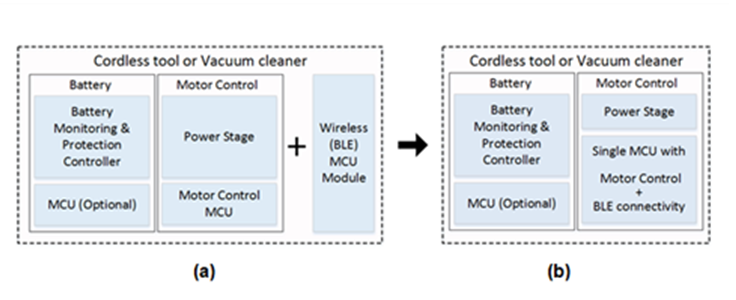
Figure 1: Existing architecture with separate MCUs (a); proposed single MCU architecture (b)
Implementing a single MCU architecture
The Single Microcontroller 18-V/600-W BLDC Motor Control Reference Design with Bluetooth Low Energy 5.0 demonstrates the integration of TI’s DRV8323and CC2640R2 on a single PCB, enabling a single MCU to provide trapezoidal motor control and wireless connectivity.
The 1xPWM control of the DRV832x three phase gate driver family reduces the peripheral and processing overhead on the MCU for motor control. The 1xPWM control uses six-step block commutation tables that are stored internally to the gate driver; thus, only one PWM timer and two GPIOs (one for direction control and other for motor-brake control) are enough to achieve trapezoidal control with position sensor feedback. The integrated multilevel protections of the DRV832x help the designer to implement necessary motor drive protections without MCU involvement.
The SimpleLink™ CC2640R2 Bluetooth low energy wireless MCU chip has a 32-bit Arm® Cortex®-M3 core and an autonomous ultra-low power sensor controller to help you achieve reliable, robust and noise-tolerant RF performance for Bluetooth low energy 4.2 and 5.0. The MCU runs the motor with a rich set of peripherals, such as four general-purpose timers, a 12-bit 200KSPS ADC and communication interfaces like UART, SPI, I2C etc.
The reference design uses the TPS70933 linear voltage regulator to derive the 3.3V supply for the MCU. The stable 3.3V supply from the TPS70933, and the layout with single-point grounding, ensure that the CC2640R2F has a clean power supply and a stable ground reference to protect against noise from the power switching.
The Single Microcontroller 18-V/600-W BLDC Motor Control Reference Design with Bluetooth Low Energy 5.0 offers a SimpleLink Bluetooth 5.0 option with better industrial noise immunity, more range and less power consumption for applications such as power tools that operate from a five-cell lithium-ion (Li-ion) battery. The design demonstrates Bluetooth low energy receiver sensitivity of -96dBm even when the power stage is driving the motor, showing the robustness of RF performance.
Figure 2 shows the reference design board image and block diagram.
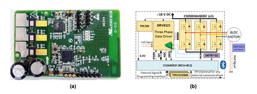
Figure 2: Reference design board (a); and block diagram (b)
Table 1 lists test results with the reference design, showing the received signal strength indication (RSSI) considering a packet error rate (PER) of 30.8% at three frequencies. The sensitivity levels do not have a noticeable difference when the motor-drive power stage is disabled and enabled.
| Bluetooth low energy channel frequency | RSSI (only Bluetooth low energy; motor drive disabled) | RSSI (Motor on, motor current = 15A |
| 2,402MHz | -95.2dBm | -94.9dBm |
| 2,440MHz | -95.7dBm | -95.4dBm |
| 2,480MHz | -95.8dBm | -95.7dBm |
Table 1. Reference design sensitivity – RSSI for a PER of 30.8% at different Bluetooth low energy channel frequencies
Figure 3 shows typical transmitter performance of the reference design in three-channel advertising mode. The noise floor is at -107.5dBm. The plots show that transmitter (TX) power spectrum when the motor drive is ON matches with the transmitter power spectrum when the motor drive is OFF.
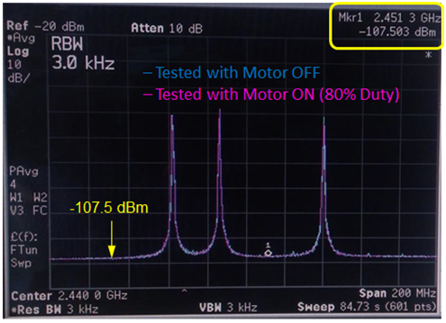
Figure 3: Reference design transmitter performance, with the SimpleLink CC2640R2F wireless MCU in advertising mode
A single MCU architecture brings many benefits to your designs. One benefit is cost savings. A single MCU for motor control and Bluetooth low energy connectivity reduces the overall bill of material, enables a single small-form-factor PCB and longer battery life than a two chip solution.
Another benefit comes from the Bluetooth low energy connectivity, which offers complete tool status, not just status about subsystems. You can authenticate users, track equipment operation for field studies and optimization, track equipment locations for anti-theft protection, online parameter configuration, all with better industrial noise immunity, more range and less power consumption.
The article first appeared on Texas Instruments Blogs.


