


LED replacement bulbs are now firmly established in the worldwide lighting market with solid state lighting options available for all major household fixtures and formats. LED bulb performance has always been excellent right from their first introduction, and has solved almost all of common compact fluorescent (CFL) bulb issues from slow starting to temperature sensitivity.
Aside from some specialty products, CFL bulbs are not dimmer compatible. A majority of LED bulbs meanwhile, to an extent claimed by the manufacturers, are dimmer compatible. In the US, the California Energy Commission (CEC) is moving to make dimmer compatibility a standard feature of LED bulbs for the Californian market.
Dimmer compatibility is the single biggest challenge facing the LED driver designer. Operational requirements with and without a connected dimmer are difficult to meet with a single design approach. Good dimmer compatibility does not lend itself to high power factor and low THD. The optimum design needs multiple personalities depending on the operating state, and enough intelligence to recognize the different operating states. Semiconductor manufacturers are releasing new LED drivers that ease the challenges of dimmer compatibility.
Types of phase control dimmer
The input filter of an LED driver plays an important role in dimmer compatibility. There are two main types of phase control dimmers: leading edge modulated and trailing edge modulated. With a leading edge modulated dimmer, the line current is delayed from the zero crossing. In this case, dimmer turn on modulates the leading edge of the current to control the bulb. Trailing edge dimmer current turns off partly though the line cycle. Both techniques are equally effective at dimming the bulb, however, the implementation for each technique is quite different.
Leading edge dimmers are much more common because their designs are much older and lower cost because the main switch is a TRIAC or SCR. TRIACs and SCRs can only be turned off when the current through the device drops below the holding current. This occurs naturally at the zero crossing after the device has been turned on. Trailing edge dimmers use MOSFETs to control the current. MOSFETs can be turned on or off regardless of the current through the device which makes them able to turn off partly through the line cycle. The MOSFETs and their associated control are more expensive and complicated than the TRIAC/SCR controlled dimmers. Not only have TRIAC/SCR dimmers existed longer than MOSFET dimmers but they are lower cost and still dominate the dimmer market. While this is great for the consumer, TRIAC dimmers present a host of complex issues for the driver designer.
Incandescent bulbs have some non-linearities that make them well suited to TRIAC dimmers. In particular, positive temperature coefficient and light output that drops off rather sharply with applied voltage. The positive temperature coefficient comes from the tungsten filament. As the tungsten cools, its resistance goes down. This makes the current almost constant over the dimming range providing hold current for the TRIAC.
Light output from a tungsten filament drops rapidly as the filament cools. Typical filament temperatures are 2,500K which puts them in the warm spectrum of light (more red). As the filament is dimmed, the power in the filament drops but also the color temperature further shifts into the red region. Incandescent bulbs are good examples of nearly perfect black body radiators. The human eye is less sensitive to red light so the luminous output from the filament drops because of lower power and color temperature shift. Light output is measured in lumens which is photopically adjusted for the response of the human eye. The human eye is most sensitive to green light at 560nm.
This explanation serves to help understand why TRIAC dimmers are so well suited to work with incandescent bulbs. No light driver (LED or otherwise) behaves like an incandescent bulb. The single biggest challenge for any type of electronic light source driver is maintaining sufficient hold current so that TRIAC does not stop conducting from current starvation. A typical 60W incandescent bulb will produce 800 lumens. An equivalent LED light source consumes only 8W to produce the same light output. The reduced input current is the chief cause of TRIAC dimmer problems. The driver must draw continuous current of a high enough magnitude over the line cycle to keep the TRIAC conducting. The EMI filter design is a critical part of this and need close attention. Some designers have resorted to complex dampening circuits that contain active components to reduce dissipation or acoustic noise. These offer performance advantages over more standard EMI filtration schemes, but do add cost and complexity.

ON Semiconductor’s NCL30095 and NCL30167 devices are examples of drivers that have been developed to deal with the issue of dimmer compatibility in LED lighting applications. The NCL30095 is a fully integrated switcher solution phase-cut dimmable LED driver in a boost configuration. Phase-cut may be either leading edge (typical for most TRIAC based dimmers) or trailing edge (dimmers compatible with electronic transformers). The internal HV MOSFET has a nominal Rdson of 4.5Ω.
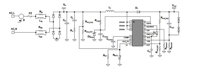 Figure 1: NCL30095 Application Schematic
The NCL30167 has the same functions as the NCL30095 except that the HV MOSFET is external giving compatibility with higher power applications. The cascoded FET arrangement is one of the unique features of these LED drivers. Output current is regulated for SSL7a compliance and included functions of the NCL30096/NCL30167 are: closed loop current regulation, thermal foldback, conduction angle sensing, mode changes, and ZCD sensing. The power stage operates in CrM.
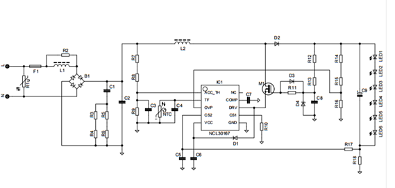
Figure 2: NCL30167 Application Schematic


")


