


For nerds like me, looking at an elegantly designed circuit schematic is like looking at a piece of art from a master craftsman. While anyone can enjoy a piece of art, if you know what to look for, your enjoyment can be enriched by finding hidden deeper meanings and signature trademarks from the artist. The same is true for circuit design. While learning to read a schematic might not lead to an emotional experience on par with taking in a Da Vinci or a Michelangelo, it does allow you to more quickly understand a circuit once you realize that design elements are often repeated across many circuits.
You are probably already well aware of quite a few of the most basic design patterns used in circuit design. The notion of series and parallel components is one such example. A voltage divider is another and is perhaps a really good example of the idea that, regardless of a how it’s drawn on a schematic (Figure 1), a voltage divider always performs the same function. The output voltage of a voltage divider will always be a fraction of the input voltage and proportional to impedances of the two components involved.
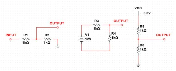 Figure 1: Three different ways to draw the same voltage divider circuit.
An RC filter is another example of a circuit that should be easily picked out in a schematic. If we keep in mind some first principles of those components, we can assess how the circuit will work without having to do any math. Recall that a capacitor acts as a show circuit to arbitrarily high frequencies and as open circuit to DC. Depending on the arrangement of the resistor and capacitor, we will either have a low pass or a high pass filter (Figure 2).
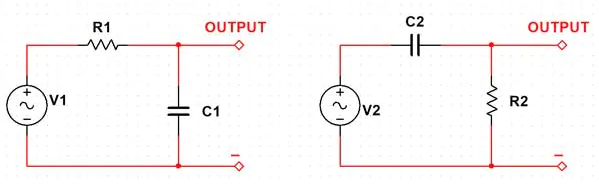 Figure 2: RC filters: Low pass filter on the left; high pass filter on the right.
So for example, in Figure 2, the circuit on the left is a low pass filter because as the frequency increases, the reactance of the capacitor drops and begins to dump the signal to ground. Thus, it passes low frequencies while blocking high frequencies, making this arrangement a low pass filter. Of course, math is necessary to determine the exact component values for a given frequency of interest. But again, the point is that when looking at a circuit for the first time we simply aim to get a general “gut feel” for what is going on. Can you see why the circuit on the right is thus a high pass filter?
Now let’s take a look at the operation amplifier (op amp) circuit in Figure 3:
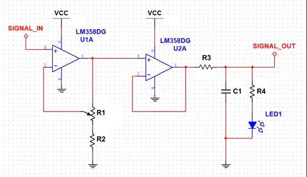 Figure 3: A basic op-amp circuit.
This circuit is a pretty straightforward and basic analog signal amplification circuit. It has been drawn in such a way to emphasize that there are three discrete but interrelated phases:
- Amplification Stage: We see immediately that there is an op amp with some sort of feedback circuitry being used. Thus, we can assume we are doing some amount of signal amplification.
- Buffering Stage: The output of the first op amp is fed into the input of another op amp. But notice this time that, while the output of the second op amp is being fed back, there are no additional components. Therefore, our op amp is likely applying a gain of one (1), or, in other words, it’s simply buffering the input signal.
- Filtering Stage: Lastly, we notice an RC network. Based on our previous discussion, we can assume that these components are acting as a sort of basic filter. Given their arrangement, we can also assume it’s a low pass filter and therefore, the filter is being used to knock down any high frequency noise.
Circuits may not always be drawn out in such a clean way in a real-world schematic. With time and enough exposure to different schematics, you will begin to see common design patterns emerge again and again. You will also understand their functionality without having to completely examine a circuit mathematically.
Building an intuitive understanding of circuits and components is equally as important as being able to analyze a circuit’s operation mathematically. It’s a skill that can really only be gained with experience. You can pick up a copy of The Art of Electronics from Mouser which is a great tome of knowledge and circuit examples to help aid in that journey.
Your turn to share. What are some tips and tricks you have picked up in learning the art and science of electronics design? Let us know in the comments down below.


")


