


Demand for SMPS is driven by the need for greater efficiency, increased power density and lower cost. New semiconducting materials such as silicon carbide (SiC) and gallium nitride (GaN) will power future applications due to their high performance and efficiency. However, high performance materials result in new challenges, as the layout of a printed circuit board (PCB) becomes more difficult. Post-layout analysis of a “virtual prototype” is ideal for managing this challenge, but until now it required expertise with a complicated, general-purpose electromagnetic (EM) field solver.
Next-generation wide band-gap semiconductors are opening new path for power electronics industry and with new paths new challenges. To take full advantage of this technology, new tools are the need of an hour by providing insight into subtle design trade-offs that can have major impact on application performance.
Keysight Technologies added Power Electronics Professional (PEPro) software, to its PathWave Advanced Design System (ADS) that enables designers to visualize effects of switched-mode power supply (SMPS) designs without the need to build and test time-consuming prototypes.
The Power Electronics Professional, Momentum, FEM Element (PEPro) is the next generation EM-circuit co-simulation platform for SMPS designs. It makes post-layout analysis as easy as pre-layout analysis. It includes automatic setup that previously required an expert. In addition, it offers pre-built analyses of effects such as voltage spiking and electromagnetic interference (EMI). It’s tailor-made for solving the challenges that SMPS designers face in this high switching speed era. PEPro revolutionizes power converter design for Power Generation and Transmission, Aerospace-Defense, Automotive, Data Center, Consumer Electronics, and IoT applications by seamlessly integrating EM with circuit simulation to become the industry’s first EM simulation platform dedicated to SMPS circuit designs.
PEPro Highlights
- New User Interface– Run a post-layout analysis as easily as a pre-layout analysis
- Expert EM-Circuit Presets– Automatic optimum settings of EM analysis and simulation controllers for switched-mode power supply (SMPS) design
- Analysis, Tuning, Optimization– Interactive EM-Circuit co-simulation, including a unique circuit excitation technique to pinpoint layout problems like current crowding.
- EM Simulation Technologies– Finite Element Method (FEM) and Method of Moments (Momentum)
- Integrated in ADS – No need for external EM simulators
- Net-based selection: no more tedious “cookie cutting” & cleanup for separate EM analysis
- No more errors from manual re-assignment of EM ports and materials
- No more tedious re-import and stitching of EM results for EM-Circuit co-simulation
- No need to learn another unfamiliar tool or wait for someone to run external batch EM analysis
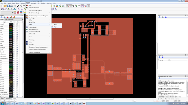
New User Interface
PEPro offers predictive expert settings for correct EM analysis of physical circuit layout structures every time. Automatic EM-Circuit co-simulation partitioning integrates EM results effortlessly into circuit design for interactive tuning and optimization.
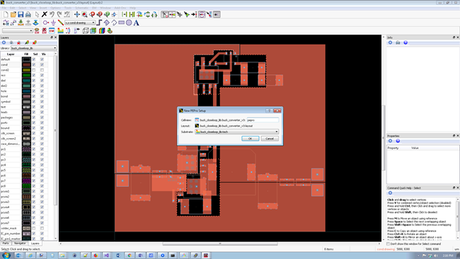
Expert EM Presets
Run an EM simulation in any portion of your PCB or module layout in situ without worrying about how to set up the analysis. Instantly use the EM results in your circuit design workflow. Account for, or even exploit EM-Circuit interactions to quickly explore innovative design options that would be impossible or very tedious to do with other tools.
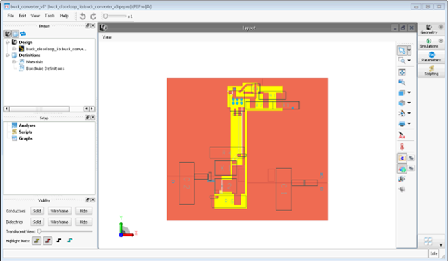
Analysis, Tuning, Optimization
PEPro’s seamless integration into ADS means no “cookie cutting” and clean-up of layout for offline EM analysis. This eliminates hours, days, and sometimes weeks of manual work preparing your layout to run an EM simulation. Therefore, you can interactively tune, optimize and analyze your design to understand the impact of well-known physical effects such as laminate registration and fabrication over- and under-sizing.
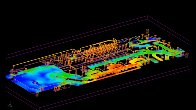
EM Simulation Technologies
Traditional circuit simulation is no longer adequate for the design of SMPS because of increasing switching frequencies, high di/dt edges, and technology integration density. The physical aspects of the circuit tend to interact more closely as complexity increases, which means that EM effects become a first-order contributor to circuit performance and must be considered in all stages of the design process. The PEPro platform unifies full 3D finite element method (FEM) and 3D planar method of moments (Momentum) EM simulation technologies for easy choice of solvers to analyze physical structures efficiently and get accurate answers quickly.
Additional information about Keysight’s Power Electronics design solutions is available at http://www.keysight.com/find/eesof-power-electronics.
Note: Pre-production PEPro is available to select customers under the Early Access program for ADS. The production version is scheduled to ship in summer, 2019.


")


