


Abstract: This article demonstrates the construction of a 10 W practice guitar amplifier circuit including a possible cabinet design to enclose the speaker circuit. It also aims to explain the working and theory behind the circuit design.
Introduction
Guitar amplifiers are electronic devices used to amplify the signal strength of a pickup attached on an electric guitar or on an acoustic guitar. A guitar amplifier produces sound through a loudspeaker which is typically enclosed in a wooden or Styrofoam cabinet. These amplifiers also enable guitarists to control the volume, tone and distortion of the guitar by enhancing or de-enhancing the tone frequencies.In this particular article, we will seek to understand and build a 10W guitar amplifier.
PREREQUISITES
WORKING OF THE AMP
The signal input to the amplifier is initially fed through a ¼” audio jack that produces a mono audio jack that does not differentiate between the left and right speakers audio input. The input signal to the audio jack is given from an electromagnetic pickup. These guitar pickups consist of hundreds of coils. Each coil is made up of resistors and inductors connected in series with each other which are in turn connected to a capacitor in parallel to the above combination. A guitar pickup works on the basis of Lenz’s law which states that the direction of induced current is always opposed to the change in magnetic flux produced by the circuit. Guitar strings of an electric guitar get magnetized by the coil. The movement of the guitar strings produces a certain source voltage (Vs) which then obeys Lenz’s law to produce the electric signal (V) to the audio jack.
Any guitar amplifier consists of 3 main circuits, that is volume, distortion and tone circuits.
Guitar amplifier schematics and circuits

The Tone Circuit
The tone circuit makes up the first stage of the guitar amplifier. It consists of IC TL072 which is a JFET and also known as a dual operational amplifier. The current schematic has a sliding capacitor which forms a potentiometer on the feedback loop of the op amp. Sliding the capacitor to the left most position of the potentiometer increases the bass of the tone of the guitar, so it consequently enhances and amplifies the lower frequencies present in the pickup signal. Moving the capacitor to the extreme rightmost position short circuits the resistor placed on the feedback loop and removes the capacitor completely thus leading to amplification of higher frequencies, also known as increasing the treble.
The Distortion Circuit
Distortion and overdrive are guitar effects added to electric instruments typically by increasing their gain and producing a fuzzy tone. Distortion effects are mainly found only in electric lead guitars and are absent in keyboards or bass guitar amplifiers. This particular circuit makes use of diodes which form part of a clipping circuit. Two types of clipping exist namely soft clipping and hard clipping. Soft clipping also known as ‘overdrive’ is when the gain is inversely proportional to the input signal level. Hard clipping otherwise known as ‘distortion’ occurs when the signal level is restricted within a range. The clipping process involves producing frequencies that were not present in the original audio signal. A number of these frequencies can be either harmonics (whole number multiples of signal’s original frequencies) or inharmonics which in turn results in intermodulation to produce newer subharmonics.
Volume circuit
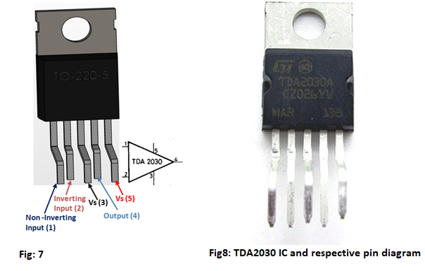
The volume circuit employs the IC TDA2030 which is essentially a low-frequency class AB power amplifier which makes it ideal for the construction of a 10W guitar amplifier.
Possible cabinet design
Guitar amplifiers normally consist of an open back so that the cabinet can add a little acoustical effect to the tone. Bass guitar amplifiers, on the other hand, have closed cabinet designs in order to obtain a better base response. A speaker cabinet design is based on several parameters known as Thiele- Small parameters that help decide the optimum cabinet size required for a loudspeaker with a certain power rating and also the requirement of the guitar.
Every speaker has a datasheet attaches to it which specifies the Thiele- Small parameters for that particular speaker. The key parameters for speaker design are the resonance frequency (Fs), the total Q factor of the speaker and the equivalent volume of air that gives the same compliance as the speaker. The speaker datasheet also includes a frequency response graph that gives us the impedance versus the frequency of that speaker. The frequency response graph helps determine the required audio output (in dB) versus a range of different frequencies conventionally lying within 20Hz to 20 KHz range (human audible range of frequencies).
CONSTRUCTION:
The circuit board can be made either with the help of a perf board or a PCB. The entire circuit consists of three major stages and hence we will verify the guitar amplifier output at each stage. Both the tone and distortion circuits make use of the same TL072 IC which is used in 2 parts among both the circuits.
A supply of 12V is ideal for VDD (power supply of the adapter). Any suitable value of voltage and frequency can be used for the input voltage from the guitar pickup.
Tone stage:
The following are the schematics for the Tone stage of the circuit. The circuit has a TL072 op-amp as discussed above and a 50Kohm potentiometer.
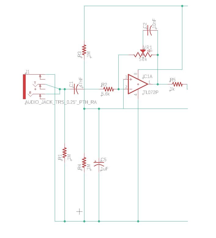
Fig2 (a): Input and Tone circuit schematics
The circuit input and output signal is displayed on the CRO below.
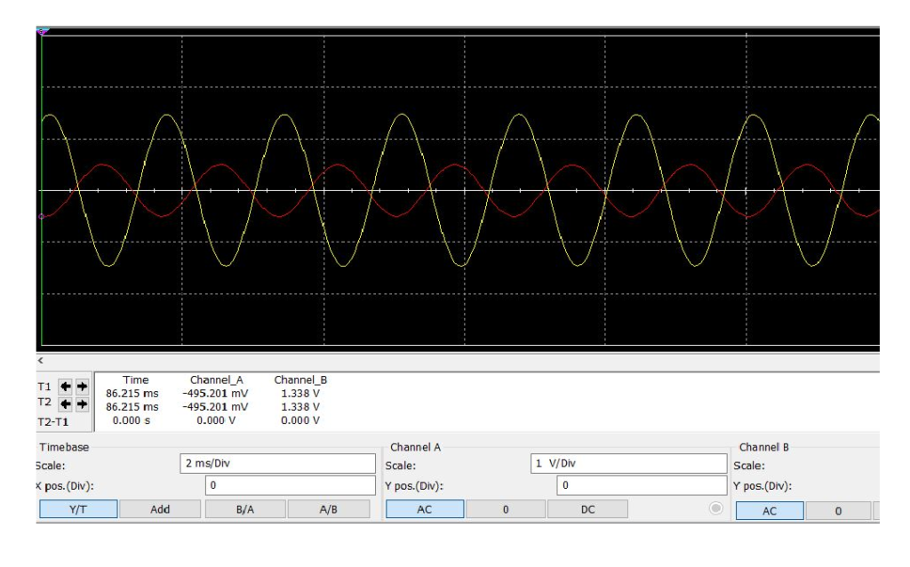
Fig2 (b): Input signal and Tone circuit output
Channel-A (red) = input signal form the guitar
Channel-B (yellow) = output signal of the tone circuit taken at resistor R5
Distortion Stage:
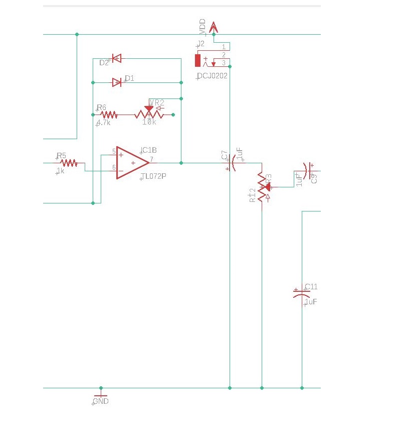
This part of the circuit involves clipping of the output waveform coming from pin 1 of the TL072 op-amp. As discussed in the working of the circuit the distortion stage uses two 1N4001 diodes in the clipping circuit and also makes use of a 10Kohm linear potentiometer. The circuit schematics for this part is given below.
The distorted output at the TL072 is shown below.
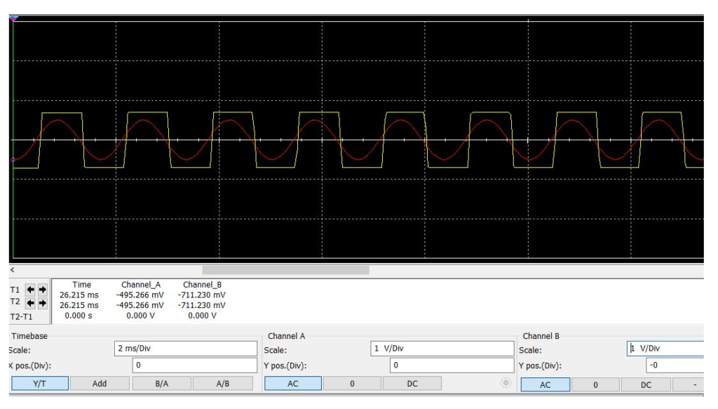
Fig3 (b): Input signal and distortion circuit output
Channel A (red): Input signal
Channel B (yellow): Distorted output signal
Volume stage:
At this point in the circuit the only job remaining is to amplify the distortion circuit output with the help of either TDA2030/TDA2050/LM386 audio amplifier ICs. The end part of this circuit is connected to the speaker.
An LED has also been included on the overall circuit schematics in order to indicate that the amplifier has turned on or off.
The circuit schematics and its corresponding CRO output are given below.
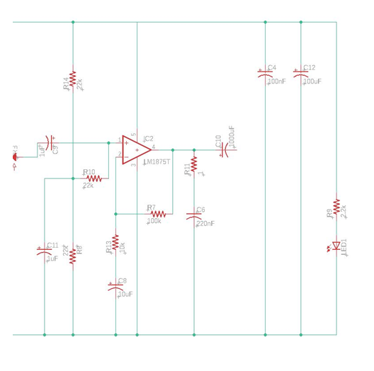
Fig4 (a): Volume circuit schematics
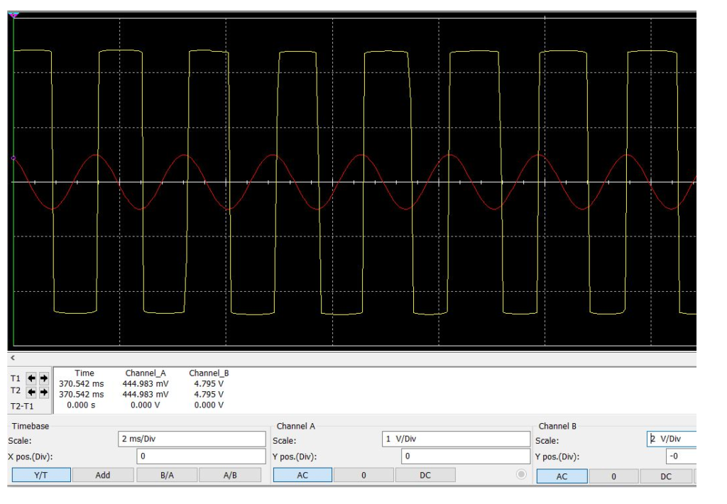
Fig4 (b): Input signal and Volume circuit output
Channel A (red): input signal from the guitar
Channel B (yellow): Amplifier output
Note: Notice the difference between the input signal and the final output. The output is distorted and has an output voltage double that of the input signal
Cabinet Design
A well-rounded frequency response will be a cabinet of volume approximately about 5832cm^3, or interior dimensions of 18cm x 18cm x 18cm.
For a bass-heavy amplifier, a cabinet volume of around 2754cm^3 will work. This translates to inner dimensions of 18cm x 18cm x 8.5cm.
Another useful way of determining the optimum inner dimensions is by following the golden ratio whose value is 0.618:1:1.618.
Parts List
| Type | Value | Qty | Markings | Directional | Direction Indicated |
| Resistors | 1 Mohm | 3 | brown black green | NO | |
| 5.6 kOhm | 1 | green blue red | |||
| 1 kOhm | 1 | brown black red | |||
| 22 kOhm | 3 | red red orange | |||
| 4.7 kOhm | 1 | yellow violet red | |||
| 2.2 kOhm | 1 | red red red | |||
| 100 kOhm | 1 | brown black yellow | |||
| 10 kOhm | 1 | brown black orange | |||
| 1 Ohm | 1 | ||||
| Potentiometers | 50KB pot | 1 | B50K (linear) | NO* | |
| 10KB pot | 1 | B10K (linear) | |||
| 10KA pot | 1 | A10K (logarithmic) | |||
| Film Capacitors | 47nF | 1 | 473 | NO | |
| 100nF | 1 | 104 | |||
| 10nF | 1 | 103 | |||
| 0.22 uF | 1 | ||||
| Aluminum Capacitors | 100uF | 1 | YES | Stripe on negative side (shorter lead) | |
| 1000uF | 1 | ||||
| 1uF | 4 | ||||
| 10uF | 1 | ||||
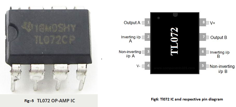
| Integrated Circuits | TL072 | 1 | See diagrams | ||
| TDA2030 | 1 | ||||
| Diodes | 1N4001 | 2 | silver stripe = negative end | ||
| LED | red LED | 1 | flat edge/short er lead is negative | ||
| Miscellaneous | IC socket | 1 | NO | ||
| switch | 1 | ||||
| wall power plug | 1 | ||||
| power jack | 1 | ||||
| ¼” Phono plug | 1 | YES | sleeve is negative | ||
| speaker | 1 | NO | |||
| perfboard | 1 |
Table1: List of required components
Pin Diagrams:
TL072:
Precautions:
- Do not plug the entire unit in until it is fully assembled.
- Do not solder the TL072 chip directly onto either a perf board or PCB but instead use an IC socket soldered onto the board and then plug the chip on it.
- Observe the polarity of the ¼” input audio jack- the ‘tip’ is the positive end and the ‘sleeve’ is a negative end. Soldering it backwards will make the amp noisier.
- In order to avoid shorting the pins of the op-amp, it will be necessary to break the connection of the metal strips under the chip. This can be accomplished by scratching the metal away with the sharp tip of a pin or knife.
- The TDA2030/2050 chip pins need to be bent slightly in order to fit on the board.


")


