Ka-Band in SATCOM
Ever increasing demand for more bandwidth in the terrestrial wireline and wireless domain on a global scale and the requirement for ubiquitous broadband network access pose significant challenges as well as chances for satellite network operators.
While spectrum is being re-farmed to enable more wireless broadband access satellite operators will increase utilization of higher band spectrum and introduce new modulation schemes to be able to increase bandwidth for future broadband services. As such satellite networks are in position to play a key role in next generation global converged communications networks.
The immanent advantage of satellite networks compared to all other networks is that they can address any geographic location at any time and from any desired location with scalable, stationary and even mobile services. Emerging mainly from broadcasting-only satellite networks have emerged to versatile and scalable media and broadband services networks.
However, higher bands, such as Ka-band, come with challenges when it comes to efficient and reliable transmission. Key for all operators is flawless operation 24/7 to ensure highly reliable services.
As one of the pioneers in satellite ground communication DEV Systemtechnik supports matching solutions.
Rain fade at Ka-band
Ka-band in satellite communications plays an increasing important role today. However, at higher frequencies, electromagnetic wave absorption increases. At Ka-band frequencies this can lead to service interruptions and performance degradations during rain fades. With high atmospheric losses, conventional fade margin approaches such as adaptive-waveform techniques or adaptive-power control techniques are not sufficient for compensation. For reliable and highly available operations, only site diversity configurations on the ground provide an adequate, fail safe solutions.
Site Diversity
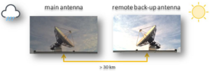
In order to mitigate the impacts of adverse weather conditions, two antenna sites for bi-directional signal transmission are linked with one main and one back up/diverse antenna configuration. Distance between main and back up antenna would be miles away ensuring they will have different weather conditions. And when one hub experiences rain or very high humidity and detects the degradation on the link, the pre-set algorithm triggers a switchover to the other hub where the ski is still clear.

Challenges:
The distance between main and diverse sites is typically larger than 30 km which demands:
Signal integrity that is provided by a high optical budget RFoF distribution system.
Precise time synchronization with tailor made delay line configuration.
Flexibility to boost the signal depending on given network conditions with EDFAs,
Switching and routing on coax domain by different size and functional redundancy and matrix switches.
Scalability for future extensions with module based systems – pay as you grow.
Easy management both locally and remotely with sophisticated interfaces.
Modular building blocks for matching configurations, optional individual customization since each site is different.
Link Redundancy Options and Required Fiber Numbers
The whole set up of all critical elements of the signal chain should be redundant. And the redundancy in such critical systems can be tailored in various ways including;
1+1 redundancy configuration
This solution not only provides antenna redundancy against rain fade but also provides protection against any risks in the long haul signal chains such as fiber damage or in the unlikely event that a system component in the signal chain has a failure. It also allows flexible and safe exchange of components during life transmission without any signal interruption. This is a common configuration in mission critical applications.

With this configuration if the there is a maintenance on the fiber that is coming from diverse site to main site and at the same time the rain fade happens at the main antenna site (means two failure is happening at the same time), it will still switch to the diverted back-up antenna by using the back-up fiber routing from diverse to main site.
n+1 redundancy configuration
At its most simple definition, N+1 basically means that there is one backup link in place for all single system component fail of a critical system. The ‘N’ in this equation stands for the number of links required to run the signal transmission system. The ‘+1’ means there is one independent backup link in case of fail of any main links.
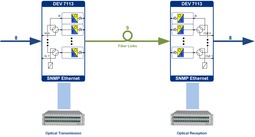
If in normal operation the RF level of one of the n main channels on the receiver side drops below the defined RF threshold, it commands the transmitter side to switch this channel to the redundancy channel.
Key Ground Station Components of Diversity Systems
RFoF Sub Systems
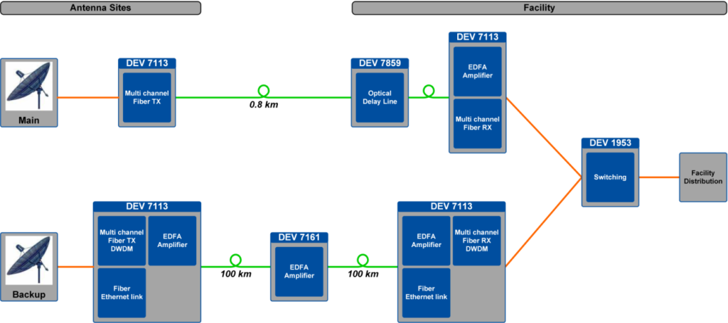
The versatile Indoor DEV 7113 space saving chassis is able to house up to 16 optical DWDM transmitter modules (DEV 7251), or up to 20 optical receive modules (DEV 7333).
DEV 7152 Outdoor Chassis has been developed for maximum reliability under harsh environmental conditions.
EDFA optical amplifier modules are available either for the DEV 7113 chassis or with 1RU standalone unit.
To ensure synchronization in time, a Delay Line is used for the local route (DEV 7859).
To control the remote antenna site equipment, DEV implemented an Ethernet Link over fiber or coax
Coax Sub Systems: Switching and Distribution
DEV 1951/1953 Universal Switching Platform for maximum system availability and reliability. Up to 16 Redundancy Switches can be populated within DEV 1953 and each switch can have its own configuration and switching mode depending on the signal type.
ARCHIMEDES L Band Matrix handles both redundancy and switching actions with a variety of modules and functions. ARCHIMEDES series comes with Fan Out (Distributing) and Fan In (Combining) options which both of them can be configured with the desired size and options.
Also DEV’s RF Splitters, Distribution Amplifiers or Combiners are used to distribute and amplify RF signals, to compensate for signal loss, and to provide redundancy functions to ensure maximum uptime.
DEV‘s Proposal

Durable, flexible and scalable antenna diversity systems for both fiber and coax domains.
Field proven end-to-end system solution.
High RF performance, long distance reach out, easy management.
All products are designed and manufactured in Germany.
7 years warranty as standard – can be further extended.
On-site and remote supervision/support from planning to installation and maintenance stages.


