


Electric motors are used to drive a wide variety of loads – fans used in air conditioning systems, pumps providing fresh water, and the motors to drive manufacturing equipment in factories are just a few examples. Traditionally, these motors were connected directly to the power supply from the utility grid. As the grid operating frequency is fixed, the motors ran at a constant speed with no direct control of the torque. Today’s motor drives use frequency inverters which control the speed and torque of the motor.
The first benefit of using frequency inverters is improved efficiency when running at full speed as the inverter can maximize torque for a given excitation current. The second benefit of allowing variable motor speed results in further energy savings. With a traditional drive, the motor was either off, or fully on (Imagine driving a car when you are only allowed to have the gas pedal fully down, or take your foot off completely). Allowing the motor to run at different speeds saves energy and allows smoother turn-on and turn-off.
Intelligent power modules (IPMs) are an enabling technology for variable speed drives and include the inverter and internal drivers in a single module. They are the module of choice for single-phase AC input applications. The transfer-molded manufacturing approach used for these modules results in excellent robustness plus power cycling and temperature cycling capability. The modules may contain a power factor correction (PFC) stage, but they generally will not contain an input rectifier stage. The ready availability of single-phase AC bridge rectifier components means that this is not a problem. The main benefit of using IPMs is that the drivers are integrated – extra pins are added for the drivers.
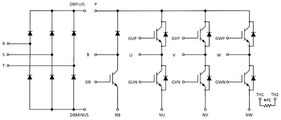
For three-phase AC input applications, IPMs become very large. This is as a result of the creepage and clearance requirements that determine the minimum spacing between conduction parts of components to stop arcing or tracking. As IPMs have extra pins for the drivers, the minimum spacing requirements make the IPM larger than a module without drivers. The creepage and clearance spacings must be carefully calculated for each application. These are based on factors such as the maximum operating altitude of the drive, the effective voltages in the system, the isolation used in the system, pollution degree and comparative tracking index (CTI) of the module and printed circuit board.
Figure 1 shows a schematic of a three-phase AC input module without integrated gate drivers. We will now review the required spacing based on a generic calculation covering most three-phase AC input motor drives.
The distances between the NTC terminals and any other terminal must be at least 5.5 mm. This distance includes the distance between the outer edges of the pins. However, the pins are soldered or press-fitted into pads. The relevant distance is between the outer distances of each pad. A wide tolerance on the hole size and a wider width of the annular pad helps to improve manufacturability but at the cost of reducing the creepage and clearance distances.
5mm clearance distances are needed between the R, S, T, DBMINUS and DBPLUS pins and any other pins. The required distances between U, V, W depend more strongly on the application. Minimum values of 2.5mm to 3mm are typical here.
Adding all these clearance distances, pin hole tolerances and annular ring sizes results in a module which is quite large – something like 70mm minimum. If the additional signals needed for the high side control on an IPM are added, the minimum size of the module becomes even larger, making it too large and too expensive to be practical for low power three phase input applications.
For low power industrial three-phase AC input applications, both IPM modules and gel-filled modules are extensively used: the IPM module not having the rectifier, and the gel-filled modules not having the driver. The gel-filled modules have a pin matrix, whereas the IPMs are generally housed in dual in-line packages. The gel-filled modules have lower thermal cycling capability, but new manufacturing approaches have greatly improved their power cycling capability. The PCB layout when using the gel-filled modules is less flexible than with DIP-mounted IPMs as the pins from the gel-filled module pin matrix tend to get in the way of the PCB routing.
The trend for new designs is to use soldered pins for both gel-filled and IPM modules driven by the more widespread availability of robot soldering equipment. Certain types of press-fit pins are susceptible to corrosive atmospheres but this problem is not seen in soldered pin applications.
Figure 2 shows the cross-section of ON Semiconductor’s new TMPIM (transfer-molded PIM) module. The first part of the manufacturing process is like that of a gel-filled module. The dies and thermistors are soldered onto a DBC and then wire-bonded. In an IPM module, the DBC and some components are soldered onto the lead frame before wire bonding. This results in less flexibility in the tooling and requires additional tools. In comparison, a TMPIM is fully flexible on the die placement and structure of the DBC as long as the pinout does not change.
The next stage is the soldering of the leadframe onto the DBC. The final stage is the transfer molding process where the module is encapsulated in epoxy. The leads are cut and then bent to shape in a process known as trim and form.
The advantage of this approach over modules where dies are soldered onto leadframes is that it is very easy to change the configuration or dies in the module. A new leadframe and trim and form tooling is required for a different pinout. As this tooling costs several hundred thousand dollars, the approach is used for modules with standard pinouts such as six packs, converter inverter brake (CIB) modules (Figure 1) and six packs with interleaved PFC.
Gel-filled modules are more flexible to change for custom approaches, but do not have the same thermal cycling capability as a transfer molded module. For the same DBC soldering and wire-bonding approach, transfer molded modules will have better power cycling capability than gel-filled modules.
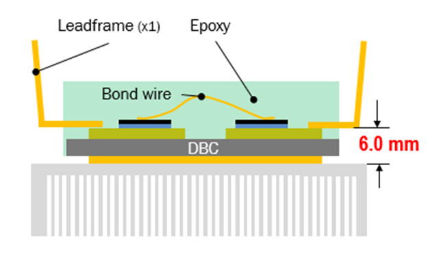
Figure 2 shows one clear advantage of the TMPIM over existing modules. The scale is stretched for illustration. The overall module thickness is 8mm. The gap between the top of the pin and the top of the heatsink is 6mm, which is greater than the 5.5mm clearance required. Gel-filled modules also meet this requirement but they are a lot thicker (12mm versus 8mm for TMPIM); IPM modules are thinner. As a result, the mechanical designer needs to shape the heatsink which typically adds extra manufacturing cost.
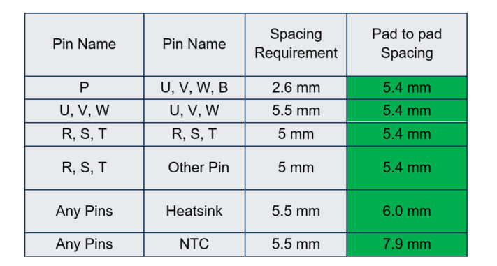
Table 1 shows the spacing between the edges of the solder pads after allowing for a 0.5mm pad ring width, 0.3mm drill tolerance and the pin size. The spacing requirements were considered extensively during the design of the TMPIM product.
The IGBTs used in the TMPIM are robust Field Stop II 1200V IGBTs with a short circuit rating of more than 10µs at 150C, 900V bus voltage and 15V gate drive. Before release, the modules were extensively tested in motor drive tests, including bench tests. The NCP57000 isolated gate driver from ON Semiconductor ® is ideal for driving the TMPIM. Six isolated drivers are used for each TMPIM. The NCP57000 has a DESAT function which detects an overload current and then performs a soft shutdown of the IGBT to prevent excessive voltage spikes from too fast turn off in short circuit conditions.
The TMPIM family can achieve well over 1000 thermal cycles. Standard gel filled modules without any heat sink can typically achieve only 200 thermal cycles. Power cycle curves for the modules show excellent power cycling capability, dependent on the change in junction temperature. For higher power modules in the TMPIM, a high performance aluminium oxide substrate is used. The lower thermal resistance results in reduced thermal change resulting in higher power cycling capability when reading off the power cycling curve.
ON Semiconductor’s current TMPIM range includes 1200V CIB modules rated at 25A, 35A, 35A with high performance substrate and 50A with high performance substrate. New designs in the series will cover 650V CIB modules, 650V six packs, 1200V six packs and 650V modules with interleaved PFC and six pack.

In conclusion, the approach used by the TMPIM family can extend the use of transfer-molded modules to higher power levels and also offer a convenient, compact, reliable solution for designers of inverters for industrial motor drives.


