


Smart Lighting has been one of the most noticed trends at this year’s Light + Building. However, it is not clearly defined what Intelligent Lighting or Smart Lighting means, how far reaching consequences it has for users, manufacturers and installers. Thomas Hauer, project engineer at RECOM Engineering GmbH & Co KG explains his understanding of these catchphrases and demonstrates a new technical approach.
For some time now, LED manufacturers have been propagating something that is called intelligent or smart lighting, but what is this all about?
Classical lighting control is typically limited to simple switches, dimmers, movement detectors and timers. Future lighting systems should be much more people-centric, run intelligently and even act autonomously to provide not only the best possible lighting conditions but also save as much energy as possible.
This article is a brief introduction to this topic with an overview how such systems can be realised and what this means for future LED ballasts and their development.
The Network
To realise an intelligent, sensor driven, lighting system you need to combine a lot of different devices into a holistic network to collect, share and make decisions based on the information received. The LED driver is no longer a simple power supply, but an active element in a system consisting of sensors and input-modules such as light-switches, occupancy sensors, colour sensors, real time clocks, building control systems and, last but not least, light intensity sensors. All of these devices require some sort of digital interface for intercommunication. The digital interface can be solved basically in two physical ways; wireless or wired.
Wireless Networks
Wireless networks like WiFi, ZigBee or Bluetooth are all based on the carrier sense multiple access approach. Carrier sense multiple access (CSMA) means that every participant on the network first checks if the submission channel is idle before it sends its message. Is the channel is currently in use, it waits for a certain time and then listens to the channel again to check if it is idle or not. To stop individual devices hogging the bandwidth, the data payload it can send is limited to a certain amount of data, so sooner or later every device will find an idle time slot.
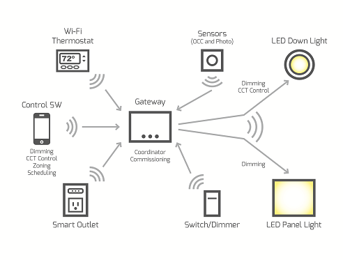
A wireless network can be realised without or with a central network master like in figure 1 shown, depending mainly on the complexity of the application where the system is used. In a domestic environment, there is rarely a need for hundreds of different scenes and pre-set configurations as required by a big theatre room or exhibition hall, so the tendency is to construct an ad-hoc or decentralised network without the need for an extensive managed infrastructure. Very simple wireless networks can be realised with a few human interface devices (HUDs) such as a smartphone or wall-mounted panel and a few networked LED lamps, but this is hardly a big improvement over the classical lighting control systems, except that it is very easy to retrofit controllable lighting into an existing wiring structure as the transceiver can be integrated into the lamp design very easily and with a very small form factor.
Wired Networks
In the wired network system, the network can be realised either with data cables or overlaid upon the power lines using for example FSK carrier data transmission. Bringing extra wires to an already installed system is often a problem because there is not enough space to put in new wires, especially in old buildings.
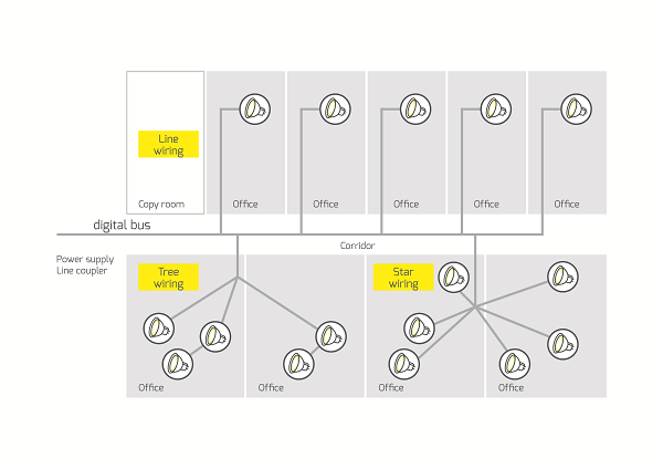
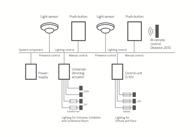
Separate data cables are much easier to include in new buildings, and once fitted can be used with a wide variety of control systems and methodologies including 0-10V, 1-10V, DALI, DMX, KNX, etc. A power-line communication (PLC) network avoids the need for rewiring, but always needs some extra interfaces and/or custom drivers to inject the control signal onto the power line and to read it off again. There are usually different standards applicable to each PLC hardware arrangement, so with very few exceptions, each installation is proprietary and incompatible with other PLC systems. As with the wireless network, in the wired world, a network can also be implemented with or without a central bus master like in figure 2 and figure 3 shown depending on the complexity of the application.
Wireless vs Wired
As described in the above introduction, there are basically two different ways to realise a network. Which one to use which and what is the best?
The biggest advantage of the wireless network systems are that there is no need for extra wiring and the system is easily expandable to include more luminaires, controllers or sensors. This flexibility arises because they are stochastic networks in which multiple information pathways can exist in parallel and the same input can be processed in different ways. On the other hand, wired data cable networks are said to be deterministic as every cause and effect is established by a fixed set of conditions and rules. This makes them inherently more stable, as well as safer against malicious interference.
As wired data cable systems operate independently, they are generally unaffected by any random events or interference generated by the other networks, be they wired or wireless. This cannot be said to be true for power line communication which uses the same set of wires for power and data. EMC is a very serious topic in PLC systems as power lines are rarely shielded. This missing shielding means that magnetic and electric fields spread out throughout the building as well as being susceptible to external EMC interference from other power devices.
Another consideration that may be important when choosing a network topology is the standby power consumption. Hard-wired data bus systems are usually very low power. For example, the DALI specification permits only 2mA current draw per device, so even a fully expanded system draws only 2W from the power supply. During inactive periods, the power consumption is merely the standby consumption of the bus power supply, typically <0.5W to meet ErP regulations. On the other hand, the specification of power line communication devices state that a typical transmitter consumes up to three watts of power to enable it to overlay a strong enough signal on top of the low impedance power lines. When considering a simple 20W LED – driver, this means 3 watts extra consumption and a decrease of 13% in total system efficiency. That is significant, especially compared to wireless applications where 100mW is the maximum permitted transmission power.
The vulnerability of wireless systems to malicious interference may sound trivial considering it is mainly used for simple commands such as light on or light off, but for complex systems such as an office building or in a theatre during a concert it could be at the very least annoying and embarrassing. For integrated building control systems that combine lighting with climate control, security door access and fire warning systems, wireless is not suitable except at the lowest possible security levels.
The susceptibility to interference arises from the basic framework of the transmission protocols. The CSMA approach on which all of these network protocols are based relies on checks if there is an idle transmission channel before transmitting the information. This collision avoidance is required because many other devices share the same frequency bands. For example, WiFi, Bluetooth and ZigBee all use the same frequency. In practice, this means that if you’re downloading something on your notebook or streaming films onto your tablet, you’re using WiFi with a high data usage where the node transmits each data packet in its entirety, thus using more payload at the transmission and so others have to wait longer.
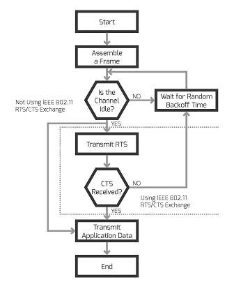
If meanwhile another device wants to use the channel, for example, to switch on the light, the actuator switch has to wait for an open slot where no other device is using the frequency (see Fig 4.)
This delay may take from milliseconds up to seconds before the lighting network can steal away an empty slot from the WiFi network.
The effect on the user is maybe the film they are watching stalls each time the light switch is activated. The reverse effect on the lighting circuit is that is also appears to stall or drop commands. The user may start to lose confidence in the lighting system and complain that it is unreliable or erratic.
The problem is exacerbated with energy harvesting wireless switches which use the mechanical energy of the button press to generate power. The energy generated is small, so each press has will typically allow the command to be sent only three times before the stored energy dissipates away.
A solution would be to use different frequencies to transmit different wireless networks, but only limited bandwidths have been released as licence-free and it is much more likely that bandwidth sharing will occur than not, especially with the concept of the Internet -of-things where hundreds of devices may be competing for time slots.
Therefore, the answer on the question, which system to use depends strongly on the application, existing infrastructure and desired security level. If there location is an open architecture with few metal or concrete structures or if the installation has to be retrofitted in a historic building, a wireless system is most likely the best choice. In a new building with steel-reinforced concrete walls and floors, a wireless network may face a lot of troubles with reflections, absorptions and losses through the building structure. In this case a wired system is more reliable. There is also the possibility of using a mixed system in an area where there are a lot of large rooms like universities and museums by using a wired backbone linking up local wireless networks. Also a mixed system can combine the benefits of the flexibility of stochastic networks with the security and reliability of deterministic networks.
The Application
Intelligent lighting gives light architects and designers more degrees of freedom to build new solutions for offices, show rooms, museums and theatres.
For example, a showroom has the task to display the best side of a product or artwork to the public, but the light levels are very dependent on the weather outside. On a sunny day the light mood is different to the mood on a rainy day, not just due to the absolute light levels but also due to the quality of the light but also due to the albedo of the object to be displayed. An intelligent (sensor driven) lighting system can use indoor and outdoor sensors to detect the light level, colour temperature and light diffusion levels and report this to the lighting system. The lighting system can then be programmed to react to adapt the lighting within the room to always present the object on display with the optimum colour rendering, light intensity and minimum energy consumption.
The same applies for museums or art galleries, but with the added complication that the system must also provide ambient lighting that is restful and pleasant for the visitors as well as adequately lighting the objects and artworks without either causing visitor disorientation due to sudden changes in light levels or damaging sensitive artworks with high UV levels. According to the information that the sensors report to the system, the lighting system can react and adjust brightness and colour temperature in each exhibition space individually depending on the occupancy levels. This level of autonomy is not new, but the ability of LED lighting to project light with variable colour temperatures and to dim without affecting the colour rendering index, added to the rapid reduction in the cost of such systems, has enables new applications in areas where it was not possible before due to technological or financial reasons.
The LED Driver
The utopian scenarios described above require a new thinking in the development of LED drivers. In the past (and still often nowadays) there is a very simple way of thinking about LED drivers, namely a different LED driver is required for each application depending on the light engine. This thinking was correct, or at least acceptable, in the past but does not hold for the future of intelligent lighting systems, where many different kinds of LED luminaires, spots, wall washers, direct and indirect lighting may need to be integrated into a single network or network of networks.
The diversity of options that may have to be integrated into an LED driver in the future has necessarily led to a new way of thinking. This new thinking is necessary because the LED driver market is a very price sensitive one and all these shiny new extras come at a price – especially when there is the need to develop a new LED driver for every application or light source within an application. If there is a new development for every application or light source, the lighting designer comes very quickly into a high mix and low volume portfolio and with such combinations the prices per LED driver rise and at some point they become unaffordable. To address this topic there has to be a universal platform design at a reasonable price.
Due to the complexity that new applications bring, it is necessary to separate the complete design problem into smaller, more manageable, parts. The first element to consider is the AC/DC ballast. The traditional solution is an 115Vac or 230Vac input voltage power supply with fixed output current. For example, a 25W LED driver might be specified with an output current of 500mA that is constant over an output voltage range of 36Vdc-48Vdc (18-24W). If the LED forward voltage is below 36V, the LED driver will not be able to drive the LED properly. Even if the undimmed forward voltage is within range, say, at 40V, this forward voltage will drop with decreased current so that the output current can become unstable at low dimming levels unless a PWM dimming scheme is used with the corresponding risk of a stroboscope effect.
A more flexible solution is a universal input AC/DC supply feeding a freely programmable DC/DC output stage. The constant current voltage range can then be as wide as 6V-40V, so all LEDs in the range of 3W to 20W can be properly driven at a wide range of pre-set drive currents. Thus the lighting designer can think in terms of LED power (10W, 20W, 40W) and not worry too much about amps and volts.
This two-stage solution has, like every technical approach, advantages and some disadvantages. The disadvantages are that the solution is more complicated and therefore more expensive and that there are more internal losses because of the extra output stage. A DC/DC stage has normally an efficiency of more than 92%, so there are not large additional losses, but there are some. This disadvantage is largely outweighed by the advantage that the LED ballast can realise a dimming range from 0 to 100% in almost every output current range that the customer wants within the maximum output voltage limit. The fact that one power supply can be used with many different LED light engines and luminaires moves away from the high mix, low volume area towards the low mix, high volume area, with a corresponding improvement in costs, lead times and installation simplicity. By adding digital or analogue dimming to this universal solution, then a truly intelligent lighting network becomes a step closer.
One of the main advantages of LED lighting over traditional lighting is the efficacy, or lumens per watt, and the long lumen maintenance lifetime, or LM80 figures. But it makes little sense to have a highly efficient Light engine with low lumen depreciation if the LED driver is inefficient or unreliable. Many early uptake LED lighting installers suffered from premature failing lighting systems until it was understood that the thermal design of both the LED light engine and LED driver are critical in determining the useful lifetime of the fixture. In the meantime, most LED luminaire manufacturers have learned the basics of good thermal design with adequate heat-sinking, good choice of TEM materials and careful passive or active cooling.
The real-life thermal performance of the LED driver is, however, much harder to determine by just looking at the datasheet figures alone. Essentially, the efficiency under the actual operating conditions is more important than the operating temperature range on the label. The efficiency will be typically given at full load (maximum output voltage) but may be very different in other parts of the operating curve or when dimmed below 100%. The additional advantage of a DC/DC output stage is that it maintains a stable efficiency over a wide range of operating conditions and dimming levels.
All LED power supplies with a power of more than 25W need a power factor correction (PFC) circuit. For the primary side, there are two topologies that are commonly implemented. The first is to use a transformer also as the active PFC to reduce size and cost. This single stage topology is simple but it needs very big output capacitors to eliminate the resultant 100Hz output ripple. The output capacitors have to be electrolytic capacitors to get a high enough capacitance and this limits the lifetime of the driver because the high output ripple current increases the internal temperatures and they suffer from aging effects. The alternative topology is to use a two stage solution with a separate boost circuit before the transformer. This boost stage then does the power factor correction and transfers the input voltage to a certain higher voltage. This voltage has the 100Hz input ripple but the transformer circuit then filters the 100Hz ripple out and on the output there is no 100Hz ripple anymore and because of that there are no big capacitors needed. What implication has this for intelligent lighting? Well, most
| Input Voltage (Vac) | Power Factor | THD (%) |
| 90 | 0.999 | 0.1% |
| 115 | 0.998 | 0.4% |
| 230 | 0.992 | 1.6% |
| 264 | 0.984 | 3% |
| 277 | 0.981 | 4% |
| 305 | 0.972 | 5.5% |
Figure 5: Measured Power Factor and THD values with Digital PFC (60W Led driver
PFC circuits, whether single or dual stage designs, use analogue controllers. A fully digital PFC controller has more flexibility to adjust to different operating conditions and input voltages to generate a power factor closer to 1 with a corresponding reduction in the THD value like in figure 5 shown.
The DC/DC stage can be realised in many different topologies as well. The most common topologies are buck, boost and buck-boost because they are a second order systems and easy to control. Which topology is the best for the design depends on which voltage ranges the LED light engines require. Independently from the choice of topology, there are still some things that have to be considered. These considerations are all about efficiency and price. A good estimation is, that the more efficiency is has to have, the more expensive it gets. In practice it is always a trade-off.
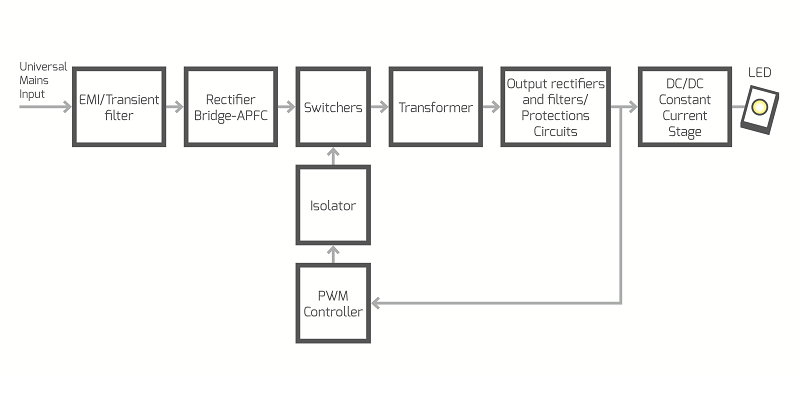
Last but not least is the consideration of how the DC/DC stage is driven or controlled. To meet the requirements for the applications discussed above, it is necessary to have a digital control circuit in the design. The last few years have shown a vast increase in the microcontroller market because of the widespread introduction of the ARM cortex and the IoT hype. This development is also very useful for the lighting segment as the cost of an integrated microcontroller incorporating core independent peripherals such as fast comparators, rail-to-rail op-amps and high resolution PWM generators has dropped to below the cost of an equivalent analogue controller solution with all of its associated components. This development is the final jigsaw piece in the intelligent lighting concept. In figure 6 the principle of such a LED driver is shown.
It showed to be the most promising solution to go for a digital solution that leaves open as much degrees of freedom as possible during the design process for a new LED driver. In each power supply there are three digital controllers. The high side digital PFC controller achieves industry leading power factor correction with ultra-low THD levels over the full input voltage range of 90-305Vac. A low-side microcontroller is used to control the LED string currents and a second microcontroller is used to handle the communication within the network of the application where the LED driver will be used. The communication between the two microcontrollers is realised with I2C standard commands. The I2C bus system is a well-established and robust internal communication bus. Furthermore, this bus system is implemented in very small 8bit microcontrollers and also in larger. More complex 32bit ones. This means a very lightweight bus system can be implemented on an 8bit microcontroller but the solution is also suitable to carry an ARM Cortex processor with some kind of embedded Linux to handle more complicated tasks. This platform design leaves it completely open to lighting architects and designers to request firmware or communication updates to easily integrate the LED driver within the intelligent lighting network.
Conclusion
An intelligent lighting concept requires several elements to be fully realised; a wired or wireless or hybrid communication network (with or without a central controller), a wide range of sensors, switches and detectors that can seamlessly communicate with each other and intelligent LED drivers that incorporate digitally-controlled power stages to drive a wide range of light engines with high accuracy, reliability and control resolution.


")


