


The STLINK-V3 is one of the best ways to debug and program an STM32 microcontroller. It transfers data faster than the previous generation and with much more flexibility, thanks in part to its STDC-14 connector and its support of a virtual COM port. Recently, ST announced the new STLINK-V3PWR, which should be available during the second quarter. Pronounced “ST LINK V3 Power”, it is the only source measurement unit with such a wide range of dynamic measurements, with a 2% accuracy across the entire range, and that is available for less than USD 200.
Previously, on the STLINK-V3…
STLINK-V3 first came to the public in the form of the STLINK-V3SET. ST then released the STLINK-V3MINIE and STLINK-V3MODS, which don’t support adapter boards but offer a smaller design for engineers looking for portability. However, all probes observe one principle: they must work regardless of unexpected edge cases or new applications. All STLINK devices thus focus on versatility thanks to a clever interface, a robust connector, and various modules to tailor our offerings to more developers.
STLINK plays a significant role in the adoption of STM32 microcontrollers. When Professor Zhu of the University of Maine presented a curriculum teaching embedded systems to undergraduates with ST’s drone kit, educators asked about the debugging tools. The drone kit is too small to integrate the STLINK interface, thus requiring an external module. The audience’s response to the new STLINK features and probe selection was overwhelmingly positive. To better understand why ST continues to release new modules, including the STLINK-V3MINIE, our first standalone probe with a USB-C port, let’s explore five reasons behind the success of our latest in-circuit debugger/programmer.
1. STLINK-V3: A Strong Heritage
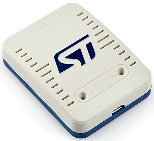
While the new STLINK is increasingly popular, ST-LINK/V2, the previous generation, continues to have a following. The first ST-LINK/V2 standalone device came out in 2011. It meant that developers could rapidly connect the in-circuit debugger/programmer between their board and their PC to compile their code, send their application to their MCU, benefit from unlimited breakpoints in RAM, and figure out if the system could run or if an error caused problems. The solution is highly popular amongst professionals and large engineering teams. Consequently, we continue to sell and support our ST-LINK/V2 devices as companies transition to the new interface.
Our investments in ST-LINK/V2 also serve as a witness to our commitment to longevity. Teams pondering whether to adopt or switch to the latest STLINK can simply check our track record. We’ve launched at least one new probe every year to meet new demands. Whether to help developers work with low-power microcontrollers, enjoy a smaller form factor when they are on the go, or adopt new ports, like USB-C, ST continues to improve version 3, knowing that, just like ST-LINK/V2, the interface will continue to live on for a very long time.
2. A Faster In-Circuit Debugger/Programmer
Data transfers are the bread and butter of this platform, which explains why the first significant architectural difference between ST-LINK/V2 and STLINK-V3 is the latter’s compatibility with the USB 2.0 Hi-Speed interface. Previously, developers had to contend with a 12 Mbit/s USB 2.0 Full-Speed data rate, which could be cumbersome when uploading large applications. Comparatively, the latter offers theoretical speeds of up to 480 Mbit/s.
Furthermore, beyond the simple interface upgrade, ST also implemented multiple optimizations of its algorithms and processes, making this a thorough architectural overhaul instead of a simple speed bump. Hence, the increase in productivity for teams that upload large applications multiple times a day is highly noticeable.
Beyond better speed, all STLINK-V3 boards, except for the daughter cards, offer mass storage support for a more convenient upload process. Previously, only the ST-LINK/V2 available on some of our development boards, like our Nucleo boards, offered this feature. However, with the new probes, engineers can connect the in-circuit debugger/programmer and then drag and drop binaries to upload them in no time. This is particularly useful for developers wanting to experiment with a demo application on a custom PCB quickly and who would rather not have to compile their code and send it through their IDE. It also makes swapping demos far more convenient, especially in the field.
3. A More Flexible Tool
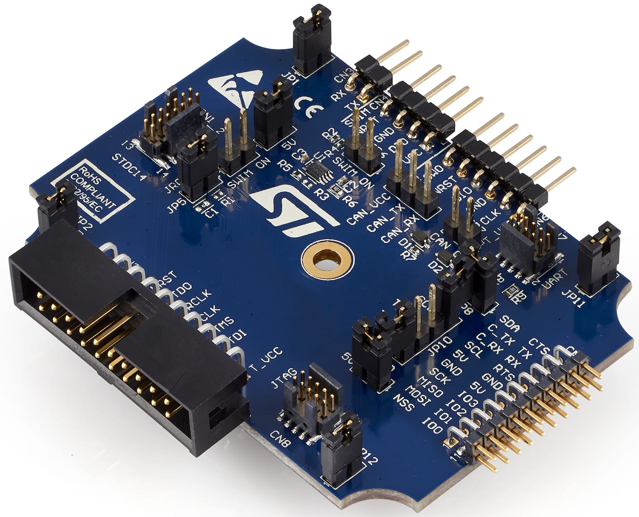
The ST 14-pin debug, the STDC-14, present on the STLINK-V3SET, the B-STLINK-VOLT, the B-STLINK-ISOL, and the STLINK-V3MINIE is another reason for the modules’ flexibility. When users open the packaging of the STLINK-V3SET probe, they will find the traditional MIPI 10-pin cable, which is relatively compact and very popular, and a new STDC 14-pin cable. The MIPI 10-pin version doesn’t support a virtual COM port. As a result, we developed an extension of the MIPI-10 connector that uses four additional pins to offer more features.
This is important because until now, engineers had had to use extra cables and find workarounds to get a virtual COM port when they didn’t have the ST-LINK/V2 built into their development board. Thanks to the STDC-14, using a virtual COM port is more practical. Similarly, the in-circuit debugger/programmer opens the door to an entirely new set of features, allowing PC developers to drive a couple of GPIOs from the new ST-LINK thanks to the DLL API present in STM32CubeProgrammer. Hence, teams can potentially add LEDs that light up as a sign that a routine runs well, control other peripherals, or even use proprietary extensions via these IOs.
4. A Versatile Companion
The new architecture is more versatile than the previous generation thanks to its support of JTAG (Joint Test Action Group) and SWD, as well as the STDC-14 connector and its virtual COM port. Moreover, the STLINK-V3SET goes further with the ability to add extension cards on the debugger/programmer, such as the B-STLINK-ISOL and the B-STLINK-VOLT (more on them later), to increase its functionalities.
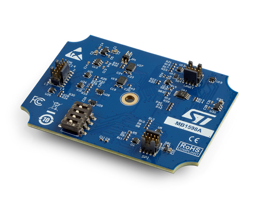
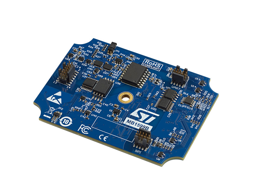
Another example of our platform’s flexibility is the availability of a complementary interface board that allows developers to upload firmware through the SPI, I2C, or UART interface. This extension card serves as a bridge between the target board and the PC. Using the STM32CubeProgrammer software tool, either in a command line or graphical interface mode, developers can use this bridge to facilitate maintenance operations without leaving a debug port open, which represents a severe security breach. In the same vein, the STM32CubeMonitor software tool provides a visual interface when using multiple STLINK probes simultaneously. Developers can thus efficiently analyze their application’s behavior thanks to a customized dashboard.
The ST Partner Program can also enhance the programmer’s journey, such as with Percepio and its Tracealyzer for the STLINK-V3. Tracealyzer is a trace visualization tool for developers of RTOS-based software systems, providing over 30 graphical views and live visualization. Tracealyzer supports all STLINK-V3 probes, providing comprehensive insight into STM32 software during development, debugging, validation, and optimization.
5. A Custom Approach to Developers’ Needs
STLINK-V3SET
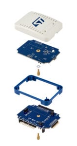
The STLINK-V3SET will attract developers with more extensive needs. The module comes with more cables as it is compatible with the larger and still valuable MIPI-20 connector. It also has a height-adjustable casing to shield the stack of boards on top of the STLINK-V3SET so users can neatly house their extension cards. The STLINK-V3SET is also the only one to offer compatibility with SWIM (Single Wire Interface Module) to ensure teams can program and debug an STM8. As a result, it is the largest STLINK-V3 probe ST currently offers and will attract engineers working in a lab or those prioritizing features over portability.
B-STLINK-VOLT
The B-STLINK-VOLT is an adapter board allowing the STLINK-V3SET in-circuit debugger/programmer probe to work with STM32 microcontrollers (MCU) that draw less than the traditional 3.3 V. Put simply, it’s a conversion circuit that lowers the voltage to as little as 1.65 V, thus ensuring developers can use STLINK-V3 with systems relying on a small battery, for instance. Users find the same STDC-14 connector to debug and program their MCU using JTAG, SWD, SWV, or VCP while still communicating using SPI, UART, I2C, CAN, or GPIOs. We also updated our user manual to cover the various jumper configurations and the board’s installation into the STLINK-V3SET case.
Until the launch of the B-STLINK-VOLT, teams using an STM32 MCU at 1.8 V had to rely on STLINK-V2. The new STLINK first focused on performance, and a voltage reduction necessarily lowered the frequency of the various interfaces. Hence, when STLINK-V3 was new, most engineers used the previous generation of probes since they wouldn’t have seen a change in data transfers. However, now that the latest version is highly popular, we decided to launch the B-STLINK-VOLT and the B-STLINK-ISOL, thus opening STLINK to a whole new range of STM32 applications. Please note that working with STM8 doesn’t require this specific adapter board since the STLINK-V3SET already includes the necessary conversion circuit.
B-STLINK-ISOL
B-STLINK-ISOL is a module for the STLINK-V3SET that offers galvanic isolation and works with microcontrollers that draw less than 3.3 V. When connected to the STDC14 connector of the STLINK-V3SET, B-STLINK-ISOL serves as a traditional debugging probe. When connected between the STLINK-V3SET and its adapter board MB1440, B-STLINK-ISOL ensures developers can access all signals and connectors on low-power MCUs. Hence, it offers similar features as the B-STLINK-VOLT but with the added benefit of galvanic isolation, which protects the PC and the board. Indeed, ground loops may cause damage or interferences when two circuits use the same ground. Galvanic isolation solves this issue.
STLINK-V3MODS
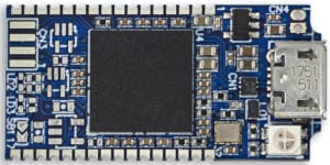
The STLINK-V3MODS is the smallest (15 x 30 mm) board and the only one engineers can directly solder onto a PCB to vastly increase their prototype’s appeal. Additionally, the board receives power through its micro-USB connector, thus simplifying its integration into a custom design. The board may even supply up to 200 mA at 5V to the motherboard through its edge connector. The system only supports 3.3 V STM32 MCUs and provides compatibility for SWD, JTAG, and VCP. The solution also supports bridge interfaces, such as SPI, I2C, CAN, and GPIOs, to facilitate communication with the embedded system. Hence, it targets developers looking for speeds and versatility in a smaller form factor than the STLINK-V3SET.
STLINK-V3MINIE
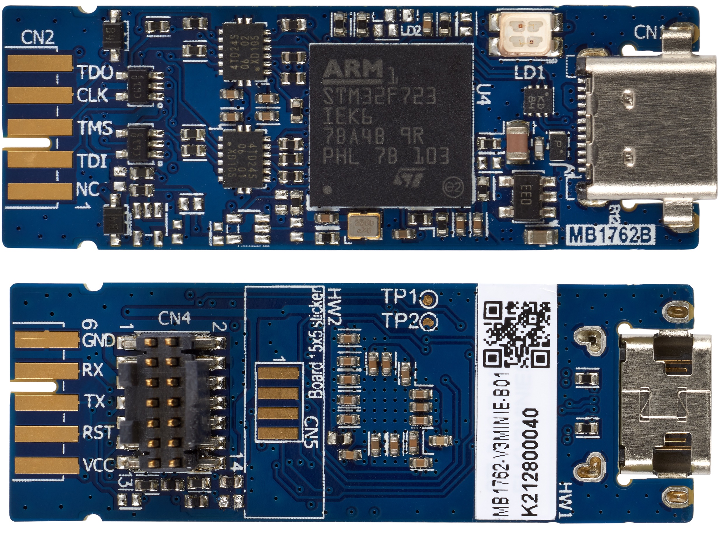
STLINK-V3MINIE is the newest model and the first to include a USB-C port. It is slightly longer than the STLINK-V3MODS at 15 mm x 42 mm; it also stands out thanks to its support for low-power microcontrollers. Indeed, it’s our first standalone probe compatible with the latest STLINK to support 1.65 V. Developers working on a 1.8 V application don’t need to grab the STLINK-V3SET and one of its expansion cards. Its small size primarily targets developers that must constantly flash firmware in the field. As a result, it supports SWD, SWV, and VCP thanks to its STDC14 connector. However, due to its size, the STLINK-V3MINIE doesn’t supply power to the embedded system.
STLINK-V3PWR
Besides traditional programming and debugging, the new probe can measure the power consumption of an STM32, draw energy profiles, and help visualize current draws to help developers optimize their code. While the STLINK-V3PWR is not the first ST tool for measuring power consumption, it is the most extensive yet. It’s also the first time ST is offering a solution that supports current measurements on all our STM32 MCUs on top of the broadest monitoring range.
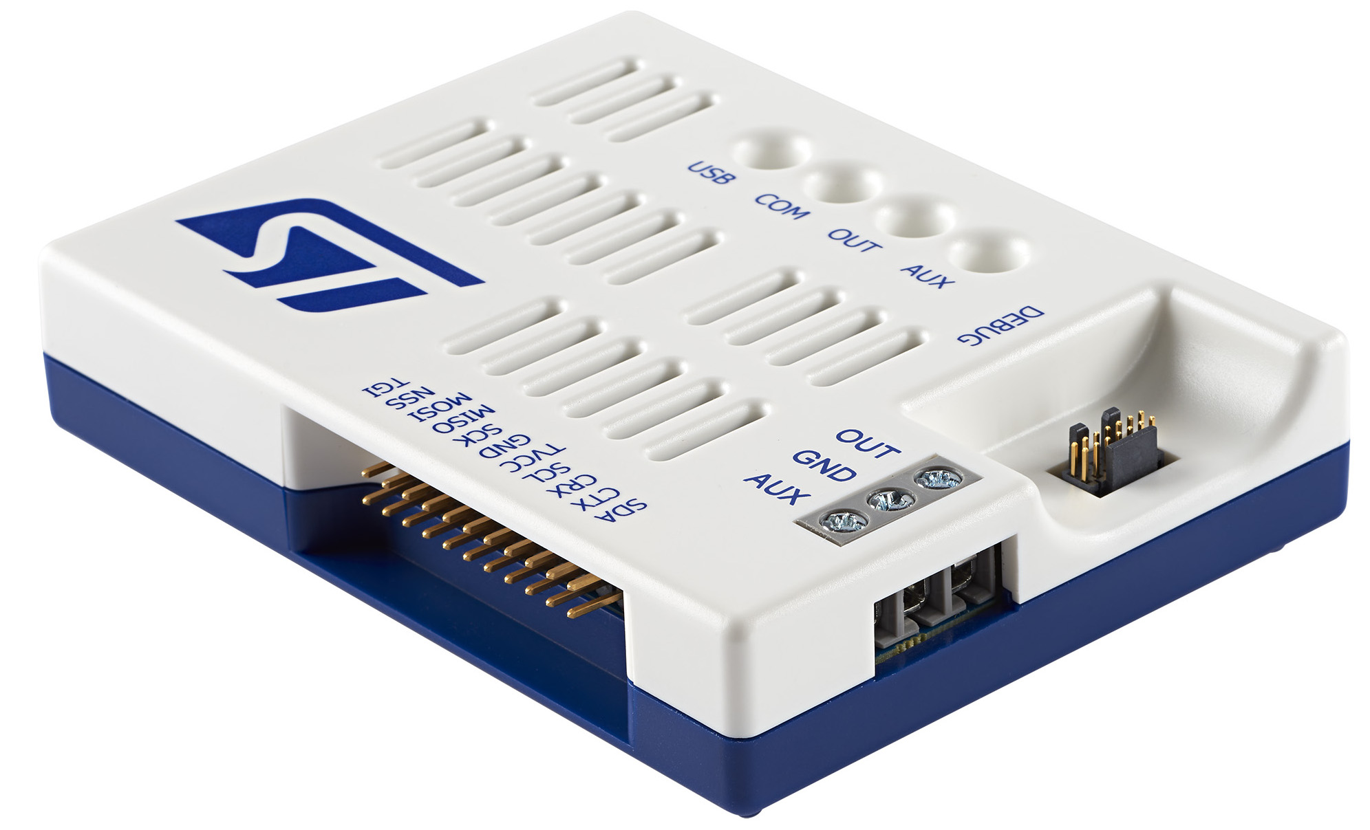
The STLINK-V3PWR can sense currents from 100 nA to 50 mA, 300 nA to 150 mA, 600 nA to 300 mA, and a 500 mA peak mode. It can also perform power measurements from 160 nW to 1.65 W with a 2% accuracy on the whole range to ensure developers can target any microcontrollers, from the ultra-low-power ones to the highest-performing models. We also provide a manual to make measurements as straightforward as possible. In a nutshell, users connect the power and ground of the STLINK-V3PWR to the correct pins on their development board and use the USB-C interface to send data to a PC.
Visualization
Engineers use measurement units to capture and visualize data. Because the STLINK-V3PWR belongs to the ST ecosystem, the most straightforward approach is to use STM32CubeMonitor-Power. The utility displays measurements in a graph to show the evolution of power consumption in real time. The software can also zoom in on specific measurements, log data over an extensive period, or run benchmarks, such as the ULPMark Bench. Keil and IAR both support the STLINK-V3PWR. ST worked with the software vendors to support their APIs and ensure the new STLINK probe would fit most workflows. Developers can thus analyze their code execution in greater depth, in sync with the energy consumption measurements, to optimize their systems’ energy profile.
Programmer and debugger
The STLINK-V3PWR remains a debugger/programmer as versatile as a traditional STLINK-V3SET, which supports JTAG, SWD, VCOM, and provides bridge capabilities like UART, I2C, SPI, or USB. Hence, teams prioritizing power consumption can use the STLINK-V3PWR as their only probe. Additionally, it can supply the target STM32 board with up to 2 A and offer over-current protection through the USB-C cable, which can be very useful when engineers are in the field and need to power their system.
To read more click here.


