


Imagine an accident has just happened in a manufacturing facility. A wayward forklift driver broke and crushed conduit carrying wires from a control panel to a pump, creating a serious short circuit. There are two possible results of this mishap:
- Result A: The pump’s control panel burst open, exposing nearby workers and equipment to intense heat and debris.
- Result B: The control panel safely interrupts the short-circuit. Once the control panel devices are inspected and any damaged devices or wiring is replaced, operation can restart immediately.
These situations are different because, under Result B, the contactor and the other components inside the control cabinet were selected based on their short-circuit current rating (SCCR) according to the amount of available short-circuit current at the installation site, along with other critical performance specs. The difference between these results comes down to how SCCR values are defined and applied.
The most common standard use to assign an SCCR to electrical control panels is outlined in UL 508A. The National Electrical Code (NEC) set marking requirements and the level of short-circuit current required for control panels. These requirements are recorded in NEC 409.110 for control panels and NEC 670.3(A) for industrial machinery. While compliance is mandatory, these SCCR values are also safety practices designed to protect equipment and personnel. Without these practices and proper SCCR compliance, the risk of damage and safety hazards increases.
Rating a device involves a series of high current tests governed by UL to validate the performance during a short circuit. The SCCR and associatd conditions are marked on the device label or instruction manual, including the SCCR current level by voltage, as well as th overcurrent protection device and size to be used for the SCCR realization. In a short circuit event, there can be a momentary inrush of current, called fault current, that can reach many thousands of amps for the milliseconds between the initial contact and current interruption by the closest breaker or fuse. The amount of potential fault current depends on the environment and the limits of upstream current. When installing a control panel in a given application, this can vary enormously, even down to individual branch circuits.
To maintain safety, a control panel must have an SCCR suitable for its environment. That rating is generally based on the individual component in the panel with the lowest applied SCCR, as it is likely has the least ability to endure during an actual incident. This indicates how much current the panel can endure, but it says nothing about fault current during an actual incident. The amount of available fault current depends on the electrical system in which the control panel is applied.
To help understand how SCCR values ensure control panel safety in industrial environments, this blog reviews the process for calculating such values and discusses how selecting the right control devices can enhance panel design while maintaining compliance with NEC and UL standards.
Calculating a Minimum SCCR Value
Determining the required SCCR for a given application starts with estimating the fault current a panel may experience during a short circuit. Typically, this involves analyzing the upstream feeder circuit, starting with the nearest power transformer. The transformer’s capacity reflects the highest possible value; however, this can be mitigated by various devices in between, and even the wiring itself, since long conductors create impedance.
Calculating the fault current of a power transformer uses a straightforward formula. In a three-phase environment:
Available Fault Current = ((kVA x 1000) / 1.732 / Secondary Voltage) / (IZ/100)
This calculation is the transformer’s secondary current divided by the impedance, expressed as a decimal. For example, with a 250kVA transformer at 480V and 4.5 percent impedance, the available fault current is about 6.7kA. This represents the highest fault current the panel could see, so many facilities will work from this figure.
The complex part is trying to determine which elements in the panel might mitigate that figure, making it possible to reduce the necessary rating. This calls for extensive calculations based on the number of factors involved, and the effect may be limited. A company’s engineers will have to determine if this rating reduction is worthwhile. Fortunately, online calculation tools can make the process easier.
This fault current rating must be applied to the panel to verify that it can withstand an incident. The first thing to check is that the breaker protecting the panel can handle the transformer’s fault current. The breaker is rated with an ampere interrupting capacity (AIC) rating. If the AIC is below the fault current, the breaker’s contacts may not open, and the short will continue until a fuse or breaker further upstream responds. Returning to the previous fault current calculation, the breaker must have an AIC greater than 6.7kA regardless of its capacity, and a corresponding SCCR.
Determining an SCCR for a panel is where the steps outlined in UL 508A come into play. Applying this to a particular application requires more detail, but the basic steps involve four subsections of UL 508A, Supplement SB:
- SB4.2 calls for examining all branch circuits and their individual power circuit components
- SB4.3 points out how to find any components capable of reducing fault current, such as fuses or circuit breakers
- SB4.4 explains how to determine an overall SCCR for the panel
- SB5.1 details how to mark the panel with the SCCR
An accurate SCCR for the panel depends on finding the weakest component (i.e., with the lowest SCCR), as it will be the first to sustain damage. Once an SCCR is finalized, the engineers must compare it to the fault current to make sure it is safe to install in the desired application. If not, there must be modifications to limit fault current or raise the rating of the lowest rated components.
TeSys Contactors Address SCCR Challenges
In control circuits, contactors are one of the components most exposed to short-circuit stresses. If a contactor fails under fault conditions, the entire panel can be compromised. For this reason, selecting a contactor with a verified high SCCR is critical.
The TeSys Deca line of contactors from Schneider Electric is designed for applications ranging from single- and three-phase motors to lighting, heaters, and other heavy equipment (Figure 1). The family of products includes models in a wide range of capacities and form factors, each optimized for specific load types and operating conditions. A common design element across the product line is the ability to endure short-circuit events without compromising safety. This feature is critical because some control panel components may be designed with lower short-circuit endurance to minimize manufacturing cost.
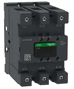
Figure 1: Schneider Electric TeSys Deca contactors enhance panel design, installation, and performance in 3-pole and 4-pole versions. (Source: Mouser Electronics)
When components from different manufacturers are combined, SCCR ratings can be hard to verify, especially when factoring installation conditions that may not be practical to implement. Standardization with clearly defined and tested SCCR performance helps avoid this uncertainty. Schneider Electric has designed the TeSys Deca product line to provide consistent SCCR capabilities, while also supporting practical configurations, long-term cost-value, and reliability.
Schneider Electric also offers an online calculation tool to determine available fault current in specific installations (Figure 2). The tool guides users through this process in a question-and-answer format and allows them to store results for future analysis. Once calculations are done for typical branch circuits, these results can serve as guidelines for developing a strategy that avoids underrating control panels.
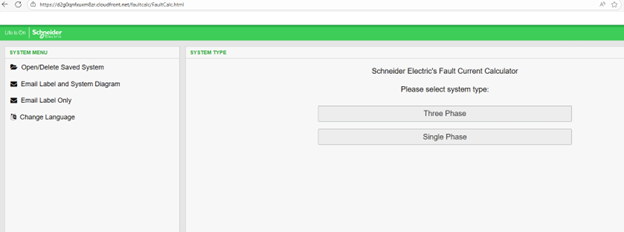
Figure 2: Schneider Electric’s fault current calculator determines the available fault current in specific installations and can store the result for future analysis. (Source: Schneider Electric)
Striking a balance between full protection and excessive costs requires engineering effort, but safety incidents and resulting damage are often far more costly.
Examples of Schneider Electric devices that address common weak points in control cabinets include:
- Type E or F combination devices: Save space, but are normally rated for 480Y/277V. TeSys Ultra combination starters, up to 20HP, can reach higher SCCR values for 480V Delta applications when used with a current limiter.
- Busbars: Busbars help distribute power across several branch circuits. Without a marking, busbars default to 10kA. TeSys Deca provides Type F-tested combinations up to 100kA as tested with it busbar accessory.
- Transformers: When a control panel’s SCCR is too low for an application, Class 7400 transformers can reduce the available fault current, thereby lowering the required control panel SCCR of the downsteam equipment.
- Disconnects: Often disconnects require the use of fuses for a higher SCCR. TeSys VLS disconnects can deliver equivalent ratings with either fuses or breakers.
- Power Distribution Blocks: Most are limited to the use of fuses to achieve an SCCR higher than 10kA. Schneider Electric has a wide range of SCCR solutions using either fuses or often preferred circuit breaker.
These examples illustrate how higher SCCR ratings can be achieved across different panel configurations.
Conclusion
Short-circuit current ratings are a major factor in control panel safety and compliance. Since a panel’s SCCR is limited by its lowest-rated component, it’s important to select devices carefully in order to prevent failures during fault conditions. Standards such as NEC 409.110 and UL 508A provide the framework for proper application, but the process can be complicated depending on installation specifics.
With properly rated components and calculation tools, engineers can design panels that meet NEC and UL requirements, protect equipment and personnel, and minimize the risk of costly redesigns.
Source: Mouser blog


