


The automotive industry makes extensive use of light-emitting diodes (LEDs) in high-beam headlights, brake and position lights, and side and rear direction lights. In an LED driver design, the brightness intensity of the various illuminating devices is not equal; rather, it depends on their specific function.
Needless to say, then, that LEDs operate at different brightness levels—for example, at full brightness for braking and from 10% to 25% for the rear lights. LED dimming circuits are used to differentiate the brightness level through a pulse-width-modulation (PWM) driving technique, which modulates the width of the current pulses applied to the LEDs. LED driver solutions integrate a PWM system to control the brightness by providing a ramp generator, thus simplifying the driver design.
PWM has been adopted as the preferred dimming technique for high-quality LED lighting. An essential aspect of the lighting control system is the power management provided by integrated-circuit (IC) drivers in several configurations, such as buck and buck-boost topologies. The ease of controlling LEDs makes them an intelligent lighting system.
LED Driver Features
LED solutions require a constant current in order to produce uniform brightness. The accuracy of the source and the fluctuations in terms of voltage and other parameters are the fundamental design parameters for the correct driver. Fluctuations that occur with the vehicle’s power supply must therefore be strongly considered. Moreover, other requirements, which are reflected in the design phase, include temperature and humidity, voltage range, electromagnetic interference (EMI) and compatibility (EMC), as well as the reliability requirements dictated by the qualification tests.
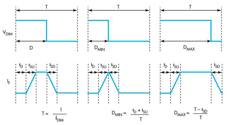 1. The delay exhibited by the LED driver is in response to its PWM signal. These delays result in the contrast ratio (CR) factor of the system. Here, tD represents the propagation delay from when VDIM (PWM signal) goes high to when there’s a response from the If (forward current) driving the LED (tSU and tSD are the LED forward-current slew-up time and slew-down time, respectively). DMIN and DMAX are the minimum and maximum duty cycle, respectively.
High-reliability demands in automotive applications indicates that protection circuitry is essential within the IC driver, which provides protection from overvoltage, undervoltage, reverse polarity, overcurrent, short circuits, and higher and lower temperatures that don’t belong in the working range. Harsh automotive environments require protection circuits to prevent problems in case of failures. The devices also should demonstrate reliable operation over an extended temperature and humidity range, and the ability to withstand continuous vibration.
The ability to adjust light intensity in interior lighting systems is a normal requirement. For outdoor lighting applications, however, the same LED must have different levels of brightness. For example, the stop and position lights or low-beam and high-beam headlights are defined at two brightness levels. In some cases, integrating a suitable driver into the design can satisfy both situations with the same LED.
The main drivers have generally been designed with integrated PWM dimming. Many chips incorporate a PWM generator to determine the driver’s ON and OFF cycle. A key factor in the PWM technique is the frequency fDIM—the minimum value of this frequency is determined by the eye’s sensitivity to flicker. Lowering fDIM generally facilitates a higher contrast ratio (CR), expressed as the inverse of the minimum on-time (Fig. 1).
Driver Topologies
LEDs typically require constant current to produce a uniform light output. Therefore, an LED driver must be able to vary the output voltage to maintain a constant current. The output voltage is related to many parameters, such as the temperature of the LED matrix and the number of LEDs in series. The designer must be able to predict with great accuracy the maximum output voltage in order to select the optimal regulator topology and, therefore, the driver IC and associated components.
The right power supply enables high-quality lighting with maximum conversion efficiency (in terms of lumens per watt), thereby prolonging the life of LEDs. The quality of the light produced is determined primarily by the light-intensity stability, which requires a precise regulation of the current with constant working points in all voltage and temperature conditions. It may be useful to employ drivers with integrated or external transistors, depending on the power of the given LEDs. However, the integration of the MOSFET for the LED driver reduces the number of external components, thus saving space on the board and simplifying the circuit.
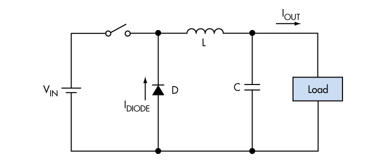 2. Energy is stored through the inductor in this buck-converter design, with the production of an output voltage always lower than input.
The LED driver can be divided into three categories: linear regulators; charge pumps characterized by a capacitor; and the switching driver characterized by an inductor (reactive electronic component). The latter have found a wide range of applications, thanks to their flexibility and ever-increasing efficiency. Moreover, they allow wide ranges of input voltage to be accepted, and have the potential to be electrically insulated for operation in high temperatures.
Linear regulators provide a simple control and don’t require filters for EMI. However, their power dissipation can become excessive for high-power applications. Switching drivers come in four flavors: buck, boost, buck/boost, and single-ended primary inductor converter (SEPIC).
As in a typical switched-mode device, a switch controls the transfer of energy. The output voltage of an ideal buck converter (Fig. 2) depends on the product of the switching cycle time and its supply voltage. The boost converter, instead, consists of four main elements: inductor, power switch (MOSFET, IGBT), diode, and capacitor.
The buck-boost configuration (Fig. 3), which employs an inductor in parallel to the input voltage, provides an advantage in terms of flexibility. The SEPIC converter (Fig. 4) topology is a buck/boost converter without the inverted voltage. It requires an additional inductor and a blocking capacitor, which is the disadvantage to this design.
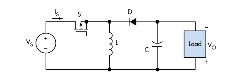 3. The inductor, which is discharged through the diode, provides current to the load in this buck-boost converter.
Depending on whether the LED application is automotive or general lighting, use of a multi-topology LED driver with maximum flexibility of input- and output-voltage range makes it easier to select the correct driver. The voltage range for the automotive sector extends from 9 to 16 V (nominal 14 V) and includes extreme conditions, such as reversal of the battery polarity (‒12 V), fault conditions like load dump (which occurs when the battery is disconnected from the alternator), and other transient voltages.
Among their other benefits, the buck-boost SEPIC configurations ensure constant brightness in all battery-voltage variations. When the need arises to control several LEDs in series, a buck-boost topology can address a variety of application requirements, including the ability to manage extreme voltage values.
In some automotive exterior-lighting applications, the LED array or matrix may be located at a distance from the driver/controller. In these cases, a boost converter can be a more appropriate topology choice. Carefully choosing the buck regulator can allow for PWM dimming frequencies in the kilohertz range. While this feature perhaps isn’t necessary for traditional lighting, it can be effective in applications such as high-speed stroboscopic effect for recognition activities (imaging) in the industrial and automotive sectors.
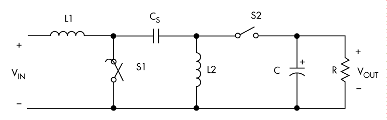 4. A SEPIC is similar to a traditional buck-boost converter, but has the advantage of a non-inverted output (the output voltage has the same polarity of the input voltage) and isolation between input and output (provided by a capacitor in series).
LEDs Create a Better Driving Experience
LED lighting and other secondary optics solutions significantly boost road safety simply due to well-lighted vision and overall improved efficiency of night driving. The characteristics of longer-duration LEDs—high performance, high brightness efficiency, and low-heat-dissipation energy consumption—are the main features of an ideal automotive lighting solution.
As more lighting technologies come onto the scene, new LED driver technologies for internal and external lighting help produce an added level comfort in a wide range of vehicles. The goal is to provide linear LED dimming with a large contrast ratio. The correct procedure is to operate the LEDs at the manufacturer-recommended forward current/forward voltage.
Conclusion
LEDs are becoming a significant force in the lighting market due to their long lifetime and the ability to control specific lighting requirements. More integration of systems-on-a-chip (SoCs) will continue to reduce the size of driver ICs, leading to faster product development cycles and accurate management of high-level lighting features.
The LED driver market for lighting is estimated to have a compound annual growth rate (CAGR) of about 27% in the near future. The key driving factors responsible for the upswing in the LED driver market includes the greater efficiency exhibited by power-management circuits and the strong demand for LEDs in commercial and industrial applications.
Source: www.electronicdesign.com


