

…and recording the data…

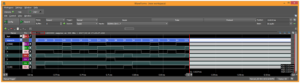
…the digits became visible. In the above image, the part of data to the left of the first red cursor is the segment signal data while the thousands digit is turned on. Zooming in on the cursor we can see the following:
Project summary
We can clearly see (pic. 10) the segment signals coming through, represented by the decimal values at the top of the bus, highlighted in blue. These are the coded values for the 7-segment display. The binary value of 1111000 mapped to GFEDCBA segments (the low logic signal is active) informs us that segments A, B, and C are on, and the digit 7 is displayed. Looking at the rest of the decimal data, we can see that counting from 0 to 9 and resetting back to 0 is done within the span of 100 μs!
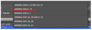
A zoomed-in big white block of data (right side of pic. 10) is shown below. That’s the data coming to the display upon selecting the ones digit, at a frequency of 100 MHz.
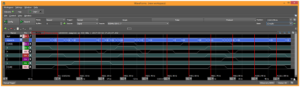
Several cursors were added to highlight the intervals. The cursors are all 10 ns apart, and when you look at the decimal value (displayed in blue at the top of each cursor), it matches the same sequence of data as the previous image. This time, counting from 0 to 9 and resetting back to 0 was done at 100 MHz. There were 8 data points between the cursors, therefore the state transitions were not precisely defined. It might seem like some abnormal data was recorded, however it should be noted that while the data on the blue line seems disrupted, several channels in that bus are simultaneously changing their states. It could also seem that these signals are not all changing at the same time.
However, something should be considered at this point… The copper traces on the Nexys 4 PCB connecting the FPGA to the PMOD output were not designed to send fast-changing signals. It means that at such speeds the physical distance between the connector and the FPGA has introduced an unavoidable signal propagation delay. This delay could be noticed in the recorded data (see above). The ability to see that is truly fascinating, especially on a device as small and compact as the Digital Discovery!
In conclusion, this project has demonstrated that the Digital Discovery is perfect for applications requiring flexibility in setting logic level thresholds, fast communication speeds (such as transmitting video signals), or simultaneously analysing up to 32 digital channels. More information can be found at Transfer Multisort Elektronik’s website (www.tme.eu).


