


Any electrical device which offers a low resistance to the current in one direction but a high resistance to the current in the opposite direction is called rectifier. Such a device is capable of converting a sinusoidal input waveform, whose average value is zero, into a unidirectional Waveform, with a non-zero average component. A rectifier is a device, which converts a.c. voltage (bi-directional) to pulsating d.c. voltage (Unidirectional).
Characteristics of a Rectifier Circuit:
Any electrical device which offers a low resistance to the current in one direction but a high resistance to the current in the opposite direction is called rectifier. Such a device is capable of converting a sinusoidal input waveform, whose average value is zero, into a unidirectional waveform, with a non-zero average component.
A rectifier is a device, which converts a.c. voltage (bi-directional) to pulsating d.c..Load currents: They are two types of output current. They are average or d.c. current and RMS currents.
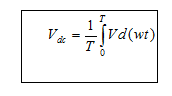
Average or DC current: The average current of a periodic function is defined as the area of one cycle of the curve divided by the base.
It is expressed mathematically as:-
- Average value/dc value/mean value= Area over one period/Total Time Period
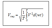
- Effective (or) R.M.S current:The effective (or) R.M.S. current squared ofa periodic function of time is given by the area of one cycle of the curve, which represents tsquare of the function divided by the base.
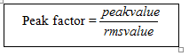
- Peak factor: It is the ratio of peak value to Rms value
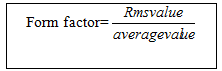
- Form factor: It is the ratio of Rms value to average value
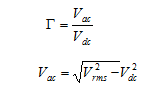
- Ripple Factor () : It is defined as ration of R.M.S. value of a.c. component to the d.c. component in the output is known as “Ripple Factor”.
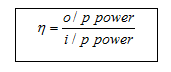
- Efficiency ():It is the ratio of d.c output power to the a.c. input power. It signifies, how efficiently the rectifier circuit converts a.c. power into d.c. power.
- Peak Inverse Voltage (PIV): It is defined as the maximum reverse voltage that a diode can withstand without destroying the junction.
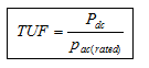
- Transformer Utilization Factor (UTF): The d.c. power to be delivered to the load in a rectifier circuit decides the rating of the Transformer used in the circuit. So, transformer utilization factor is defined as
- % Regulation: The variation of the d.c. output voltage as a function of d.c. load current is called regulation. The percentage regulation is defined as
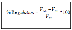 For an ideal power supply, % Regulation is zero.
CLASSIFICATION OF RECTIFIERS:
Using one or more diodes in the circuit, following rectifier circuits can be designed.
1) Half – Wave Rectifier
2) Full – Wave Rectifier
3) Bridge Rectifier
Half – Wave Rectifier:
A Half – wave rectifier as shown in fig 1 is one, which converts a.c. voltage into a pulsating voltage using only one half cycle of the applied a.c. voltage.
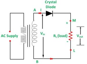
The a.c. voltage is applied to the rectifier circuit using step-down transformer-rectifying element i.e., p-n junction diode and the source of a.c. voltage, all connected is series. The a.c. voltage is applied to the rectifier circuit using step-down transformer
V=Vm sin (wt)
The input to the rectifier circuit, Where Vm is the peak value of secondary a.c. voltage.
Operation:
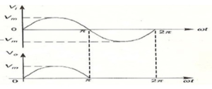
For the positive half-cycle of input a.c. voltage, the diode D is forward biased and hence it conducts. Now a current flows in the circuit and there is a voltage drop across RL. The waveform of the diode current (or) load current is shown in fig 2.
For the negative half-cycle of input, the diode D is reverse biased and hence it does not
Conduct. Now no current flows in the circuit i.e., i=0 and Vo=0. Thus for the negative half- cycle no power is delivered to the load.
FULL WAVE RECTIFIER:
A full-wave rectifier converts an ac voltage into a pulsating dc voltage using both half cycles of the applied ac voltage. In order to rectify both the half cycles of ac input, two diodes are used in this circuit. The diodes feed a common load RL with the help of a center-tap transformer. A center-tap transformer is the one, which produces two sinusoidal waveforms of same magnitude and frequency but out of phase with respect to the ground in the secondary winding of the transformer. The full wave rectifier is shown in the fig 3 below
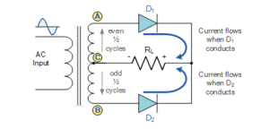
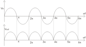
Fig. 4 shows the input and output wave forms of the ckt.
During positive half of the input signal, anode of diode D1 becomes positive and at thesame time the anode of diode D2 becomes negative. Hence D1 conducts and D2 does notconduct. The load current flows through D1 and the voltage drop across RL will be equal to the input voltage.
During the negative half cycle of the input, the anode of D1 becomes negative and the anode of D2 becomes positive. Hence, D1 does not conduct and D2 conducts. The load current flows through D2 and the voltage drop across RL will be equal to the input voltage. It is noted that the load current flows in the both the half cycles of ac voltage and in the same direction through the load resistance.
BRIDGE RECTIFIER.
Another type of circuit that produces the same output waveform as the full wave rectifier circuit above, is that of the Full Wave Bridge Rectifier. This type of single phase rectifier uses four individual rectifying diodes connected in a closed loop “bridge” configuration to produce the desired output. The main advantage of this bridge circuit is that it does not require a special centre tapped transformer, thereby reducing its size and cost. The single secondary winding is connected to one side of the diode bridge network and the load to the other side as shown below.
The Diode Bridge Rectifier
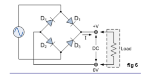
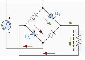
The four diodes labelled D1 to D4 are arranged in “series pairs” with only two diodes conducting current during each half cycle. During the positive half cycle of the supply, diodes D1 and D2 conduct in series while diodes D3 and D4 are reverse biased and the current flows through the load as shown below (fig 6).
The Positive Half-cycle
The Negative Half-cycle
During the negative half cycle of the supply, diodes D3 and D4 conduct in series (fig 7), but diodes D1 and D2 switch “OFF” as they are now reverse biased. The current flowing through the load is the same direction as before.
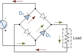
As the current flowing through the load is unidirectional, so the voltage developed across the load is also unidirectional the same as for the previous two diode full-wave rectifier, therefore the average DC voltage across the load is 0.637Vmax. However in reality, during each half cycle the current flows through two diodes instead of just one so the amplitude of the output voltage is two voltage drops ( 2 x 0.7 = 1.4V ) less than the input VMAX amplitude. The ripple frequency is now twice the supply frequency (e.g. 100Hz for a 50Hz supply)


