


A Complete Guide to High-Frequency PCB
A normal Printed Circuit Board (PCB) integrated with high- speed requirements. Since this article focuses on two fundamental words- frequency and speed, it would be an injustice to define them. Frequency refers to the number of times an event is repeated per second. Speed is how fast an entity can reach the destination. Frequency and speed are proportional.
HF PCBs can accommodate signals in the frequency range of 500 MHz- 2GHz. Thus the minimum time delay between each of the signals become less. It is between 0.5ns to 2ns that gives the immense potential to high-speed circuits and designs. High switching rates and processing speed command for the ever increasing demand for instantaneous rise times and fall times in the circuits. Closing in on the ideal condition, the high frequency (HF) circuits are a beacon of hope and stepping stone to the future. Comparing the low-speed PCB with an HF PCB- the fundamentals to the intricacies have individual compositions and specifications. A low-frequency PCB can never be used when the input frequency is in the Radio Frequency range.
Importance
When the frequency of the signal comes into play, the number of factors which had earlier been considered constant are subject to change with respect to the frequency of operation- like impedance, reflection coefficient and skin depth that changes the dielectric constant of the substrate. Causatively, issues erupt which can be effectively curbed. As the signal moves from one point (A) to another point(B), a part of the signal may be transmitted back from B. This is called reflection. This combines destructively with the incoming signal to cause a reduction in the signal strength. When the impedance of the copper wires is not matched, backflow of energy occurs. To negate this effect, the impedance of the copper wire needs to be calculated at the frequency of operation taking the length of the copper trace into consideration. An impedance matching element has to be applied in place to overcome this effect.
Secondly, if the clock of the circuit is not synchronized with the input, triggering and decoding at the wrong times happen. This leads to the wrong digital output and failure of the entire system. Interference from the passing signals through the neighboring traces may produce intermodulation products and corruption of the frequency information. If the spaces between the traces are increased the ringing reduces. However, this increases the size of the PCB. But these causes have a deteriorative impact on the efficiency of a PCB.
Consecutively, an HF PCB manufacturer has a tedious job in matching, spacing and routing over planning and placement of components. As the high-frequency signal enters the board, it needs to be given the low impedance pathway, to ensure that the critical path delay is less. Connecting using the subsequent metal layers, calculated path length and minimum distance requirements between traces enhance the PCBs operation.
As the world moves towards high-speed technology, integrating PCBs working in the lower frequency range does not deem fit. Down-converting the frequency in the operating range of PCB upstages the mere fundamental of using high frequencies. No one wants slow working mobile phones, right? With the upgrade in the technology, adapting to the newfound interest in high-frequency applications became easier. Currently, as the dimensions reduce, there are short-circuiting sending the signals to the ground and open circuiting problems, where the signal never reaches its destination. The durability of the chip is questionable, as reuse is not an option yet.
Applications
The major applications focus around communication applications like- the transmitting end and receiving of antennae- for instance- the front end of the antennae become the base stations and the mobile phone becomes the receiver. The RFIC chip inside the phone acts as a transponder with a processor, working sequentially. Satellite’s processing units use HF PCBs, as they work in the S-band to C-band of frequencies. Their corresponding earth stations also implement the same. Microwave components and amplifiers like coplanar waveguides are integrated into HF PCBs.
Materials Used
When tallying the materials to be used for the construction of the PCB, the aforementioned factors have to be taken into consideration apart from temperature, budget, and thermal expansion. The crux of all materials used by manufacturers is PTFE or Teflon as it is famously called. All the manufacturers use a modification of Teflon as the base material. Metals such as aluminum and copper are used as interconnects and mounts which increase the durability.
Roger
Rogers is one of the leading material manufacturers in the world. They are reputed for producing PCB cores for high-frequency applications. A myriad of laminates like the AD series, RO4500 series, RO4700 series and Kappa 438 series are available. They provide low loss dielectric for RF applications, high volume designs, and improved passive intermodulation. AD series are PTFE glass laminates for cost-sensitive applications. CuClad and DiClad cores are fiber-glass infused laminates while IsoClad is non-woven fiber-glass reinforcements. Kappa 438 is used for wireless technologies as an alternative to FR-4.RO3000 are ceramic filled PTFE used for commercial applications. RO4000 are hydrocarbon ceramic laminates. Encompassing all the applications, Rogers has the base for all.
High-Density Interconnect (HDI) PCBs
As the name suggests, HDIs incorporate finer lines, smaller vias, and pack more traces which allow for faster transmission. Components can be placed closer to each other than usual, and hence a number of transistors can be packed per unit area. Efficient usage of the area provided. Common applications of HDIs are in fast operation digital electronics and communication systems with the area as a constraint- mobile phones for instance.
Aluminum PCB
High power applications make use of Aluminium PCBs. They are fashionable replacements for metal cores in PCBs. They efficiently transmit heat while cooling down the circuit. Since it is recyclable, it becomes environment-friendly. Durability and higher performance also contribute to the replacement of other metal cores by Aluminium.
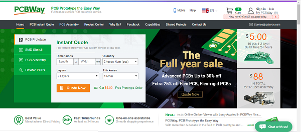
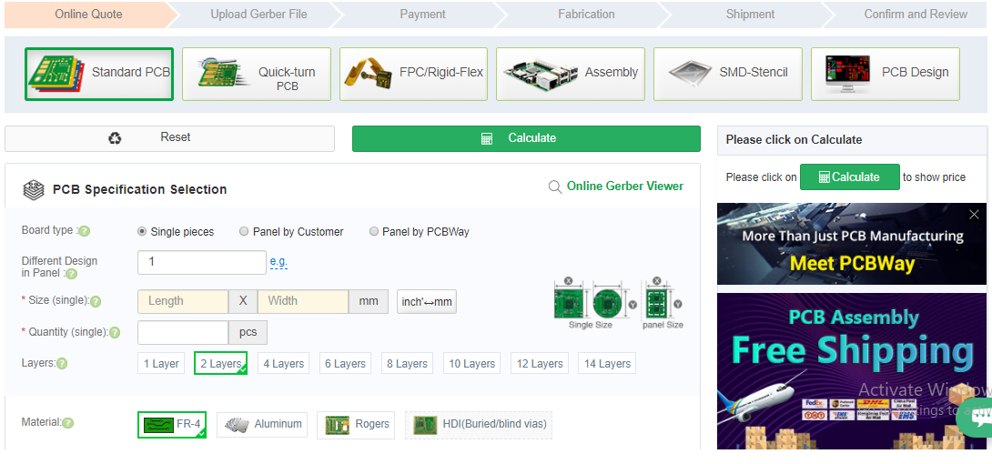
![]() PCBWay gives one of the best user interfaces for manufacturing PCBs with its instant quote application. Moving through the tabs, firstly the user comes across the specifications followed by the upload of function files and payment. PCBWay immediately analyses the quote and initiates the process. The user is updated constantly of the stage. Once it is ready the crucible is shipped to the destination.
PCBWay gives one of the best user interfaces for manufacturing PCBs with its instant quote application. Moving through the tabs, firstly the user comes across the specifications followed by the upload of function files and payment. PCBWay immediately analyses the quote and initiates the process. The user is updated constantly of the stage. Once it is ready the crucible is shipped to the destination.
PCBWay assures 100% customer satisfaction in all domains- from the ordering to the shipment. With a charismatic user-friendly website, PCBWay has paved the road to easy access to PCB manufacture to all the electronic enthusiasts around the world.


")


