


Inductor-capacitor filters are commonly added to the inputs and outputs of switched-mode power converters to reduce reflected ripple current and output noise, as well as to meet the radiation and susceptibility limits for EMC. Converter manufacturers sometimes specify a recommended filter inductor value but the performance over the full frequency range can vary significantly between different component suppliers for parts with the same nominal characteristics, leading to poor results and increased conducted and radiated interference. The variation in inductor performance is examined in this article.
Most modern power converters and certainly all isolated DC-DC converters are of the ‘switched-mode’ type, where external DC voltages are ‘chopped’ at high frequency to produce AC for the internal isolation transformer. The transformer AC output is rectified back to DC, with regulation by duty cycle control, all with high efficiency and low losses. A disadvantage is that the switching process generates high frequency ripple on the input and output along with conducted and radiated noise spikes that can disrupt other equipment. There is a trend for power converters to operate at ever higher frequencies with faster slew rates to increase efficiency, but the resulting noise spectrum is much broader.
LC filters reduce output noise
Any commercial power converter will include minimal filtering internally to reduce ripple and noise to a typical peak-to-peak value of about 1% of the DC output. This is acceptable in most cases but if lower levels are required for a sensitive application, a simple solution is to add an external LC filter (Figure 1).
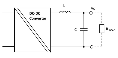
The inductor impedance is theoretically zero at DC and the capacitor impedance is infinite so the desired DC is unaffected. As frequency increases however, inductor impedance ZL increases and capacitor impedance ZC reduces, giving an increasing ‘voltage divider’ effect. The filter corner frequency is chosen to reduce ripple at the converter switching frequency, but it is more difficult to predict the attenuation of noise spikes, which comprise a spectrum of frequencies up to tens of MHz. The reason for this is that at some frequency when the value of ZL and ZC become equal, the LC network ‘resonates’ and noise can be amplified rather than attenuated, although this effect is damped by the load resistor.
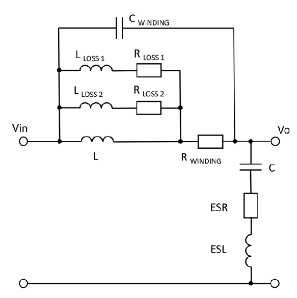
Above resonance, there is still some noise attenuation but other parasitic effects begin to occur. For example, the self-capacitance of the inductor produces another resonance, at a much higher frequency. This capacitance also tends to allow noise to ‘bypass’ the inductor. At higher frequencies, core losses in the inductor increase and AC resistance of the inductor wire increases because of ‘skin effect’, also the capacitor begins to act as a resistor as its impedance becomes small compared with its Equivalent Series Resistance (ESR). Capacitor Equivalent Series Inductance (ESL) also has high-frequency effects. If these parasitic elements are included, the equivalent circuit of an LC filter is more like Figure 2.
Parasitic effects in inductors change noise attenuation performance
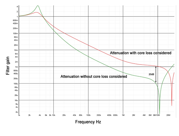
LLOSS 1 and 2, along with RLOSS 1 and 2 are a simplistic way to include the effect of frequency-dependent core losses in the circuit – different values of LLOSS give different impedances which allow different resistive elements RLOSS 1 and 2 to have an effect at different frequencies. More LLOSS / RLOSS networks can be added to make the model more accurate but component values are difficult to compute from inductor data sheet information so for a complete model for a particular inductor and core, values would be found empirically. Figure 3 shows a simulation plot of the attenuation of a filter with and without LLOSS / RLOSS networks included with some assumed values for L and C and their parasitic components, showing that core loss can have a strong effect on high frequency attenuation of noise – a difference of 20 dB at around 10MHz in this case. Unfortunately, core loss does not appear in typical inductor data sheets and can vary widely.
Input EMC filter component selection
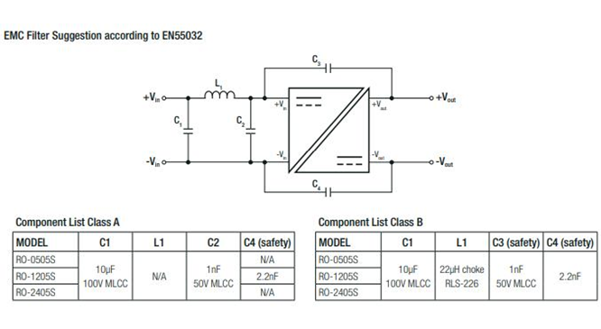
When choosing a commercial inductor for the EMC filter on the input of a DC-DC converter, (Figure 4) the inductor manufacturer’s data sheet information usually gives little more than inductance, DC resistance and sometimes resonant frequency. While this might enable the reflected input ripple to be attenuated by a known amount, the attenuation of noise spikes and their spectrum is not easy to predict without data to define the parasitic components. As seen with the output filter analysis, high frequency effects such as core loss will again have a strong influence on noise attenuation. It is understandable that the inductor manufacturers do not provide the information because there are so many variables. Core loss for example, depends on the amplitude of the AC component of the waveform and its shape. It also depends on frequency, DC current bias and temperature.
Choosing an optimum inductor is therefore difficult and at worst can lead to conducted and radiated noise levels that exceed operational or even statutory limits. This may only be found when an end-product is submitted for independent EMC testing, at which point changes are very expensive to implement.
If the appropriate test equipment is available, which might even involve antennas and an EMC chamber, samples of inductors with the same headline ratings from different suppliers can be tried in-circuit to check real-life results. A large value of inductance might seem like a good idea but the resonant frequency lowers and a physically small component is likely to have a high DC resistance which causes voltage drop, depending on converter loading and dissipates some power. Large inductors also have large self-capacitance which reduces high frequency attenuation. A final consideration is also that a large inductance itself causes voltage spikes when subject to load current steps. A smaller inductance but larger capacitor is an option but if an electrolytic type is used for cost and size reasons, it will not have very good high frequency characteristics. Other types such as ceramic are good at high frequency but are expensive and large for high capacitance values.
The right combination of L and C is a compromise affected by cost, size and performance considerations. When an inductance is chosen, there is then a confusing choice of types available in the market. There are ferrite and iron powder core types and some exotic choices such as polycrystalline cores, then there are drum, ring and ‘E’ core shapes to consider, as well as through-hole or SMD mounting options which can also affect the performance. A buyer will also see very different prices for parts which seem to have the same headline specifications of inductance and current rating.
Each inductor offered though will suit particular applications. Ferrite types have the lowest losses but the material is more expensive than iron powder for example. Iron powder is also more tolerant of over-current, maintaining its inductance better than ferrite. ‘Ring’ or toroid cores have low magnetic field leakage but are more difficult to wind and terminate than drum or ‘bobbin’ cores. Design, production, EMC, purchasing and process engineers will therefore all need to be involved to pick the optimum solution.
Solutions verified by converter manufacturers are preferred
One manufacturer of AC-DC and DC-DC converters, RECOM, has recognised the difficulty of specifying the right inductor and offers a range of low-cost inductors and recommended capacitors that have been matched with most of their power converters, with test results verified by conducted and radiated noise measurements in their in-house EMC chamber. Customers get the advantage of a proven, one-stop solution to noise reduction, saving time, money and potentially getting to market more quickly.
For more information: https://recom-power.com/rec-c-emi-inductors.html


