


Introduction
In recent years, technical innovations in the automotive field towards autonomous driving, greater electrification, enhanced safety functions, and improved fuel efficiency to reduce CO2 emissions are currently progressing, increasing the demand for smaller electrical components that provide greater functionality. And in the industrial equipment field, new functions are continually being added following the emergence of IoT such as smart factories, resulting in a significant rise in the number of mounted components.
At the same time, the advancing digitization of applications is expanding the number and role of electronic circuits, resulting in a considerable amount of man-hours spent on circuit design, from component selection during application development to board design and evaluation.
Trends in Application Design and Validation
To solve the abovementioned problems, there is an increasing tendency to use simulations in electronic circuit design. By verifying operation using simulations before prototyping the circuit board, problems can be identified in advance and can significantly reduce the number of man-hours from board prototyping to evaluation.
As a result, during actual vehicle design, not only electronic circuits but various types of simulations are utilized. And in spite of the increasing power used in electronic circuits, miniaturization is required, which can be problematic in terms of heat generation. In addition, in topologies that perform switching operation, mutual electromagnetic interference may occur, causing malfunction. And even for heat generation and EMC noise, the flow of verifying design validity through simulations has become the norm. Therefore, to simulate these factors during vehicle design, it may be necessary to provide simulation models even for component parts, obligating device manufacturers to comply. Of course, for finished products as well, evaluation and validation support may be required that calls not only for measurement of the electrical characteristics, but also the thermal and EMC domains.
Solutions for solving user issues
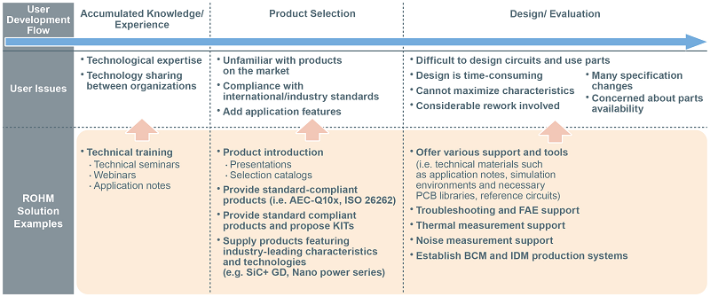
In general, the types of tools and support that must be provided for each development flow during application design will necessarily differ, so component manufacturers should be better to have the appropriate support tools and environments in place to facilitate the entire application design process.
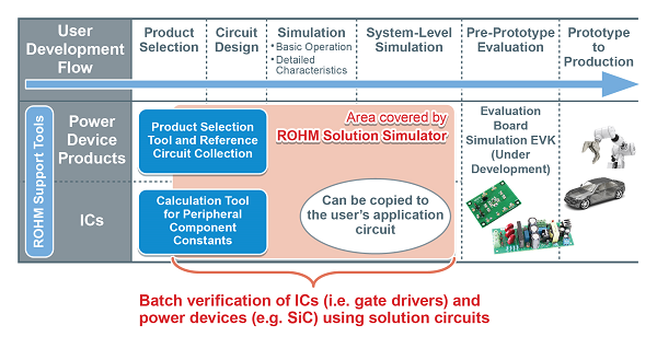
Until now, as a semiconductor manufacturer, ROHM has provided a range of solutions that contribute to solving issues for a variety of user development flows, including SPICE models that faithfully reproduce the electrical characteristics of products through simulation along with thermal design support for validating both heat generation phenomena and dissipation results using fluid analysis. Recently, ROHM has also been focusing on developing and supporting application circuits that maximize the characteristics of driver ICs and power devices designed to supply high power in the automotive and industrial equipment markets, while working to expand support for the user’s development flow. (Fig. 1)
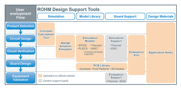
Fig. 1 shows the tools and support that ROHM can provide for the user’s development flow, with the main ones outlined below.
1) Constant Calculation Tool
To make full use of DC/DC converter ICs, it is necessary to understand the transfer functions that will stabilize the operation of the feedback circuit and determine the constants of the external circuit by taking into consideration the internal circuit constants. ROHM normally includes the theoretical formulas in its datasheets, but by using the Constant Calculation Tool, constants can be easily calculated and errors during calculation are less likely to occur. This tool is particularly suited for feedback networks such as DC/DC converter ICs and LED drivers.
2) SPICE Models
SPICE (Simulation Program with Integrated Circuit Emphasis) is a type of simulator for verifying electrical circuit characteristics and called what can express device characteristics “SPICE models”.
The Constant Calculation Tool described above can calculate the transfer functions, but estimating the waveforms is difficult unless the designer is experienced. Also, when designing the actual application, it is necessary to consider the parasitic components (wiring resistance and inter-wiring capacitance) of the circuit board. ROHM provides SPICE models that can be used under the user’s simulation environment to simulate and validate designs.
However, the parasitic components of the substrate are extremely small compared to the characteristics of the semiconductor devices, so high reliability is required for the simulation model in order to validate the effects of these minute components. ROHM SPICE models were formulated with the criteria of limiting the error of the actual device to within a few percents. A report can be provided that compares the actual device characteristics with simulated results to prove the accuracy of the simulation and ensure worry-free use.
In addition, although it is generally believed that high accuracy simulations will increase calculation time, ROHM can provide SPICE models for frequency analysis capable of high-speed simulation by leveraging original technology to extract the frequency components without performing switching operation. This enables frequency analysis to be performed in less than a second – the fastest in the industry* – significantly reducing analysis time.
ROHM also plans to release unencrypted SPICE models that can be validated using general SPICE software, allowing users to carry out independent verification using their own simulation tools.
* ROHM Study as of April 2020
3) EMC Simulation SPICE Models
Particularly in the automotive field, electromagnetic interference between devices can cause malfunctions. A typical standard designed to prevent this is CISPR25. Many of ROHM’s key products are evaluated using CISPR25 compliant methods to support measurement and provide improvement proposals when noise issues arise in user applications. ROHM has begun offering SPICE models for EMC simulations, and will continue to expand its lineup. We believe that we can significantly reduce the number of board revisions by providing simulation support for EMC designs that typically require repeated board modification and product selection.
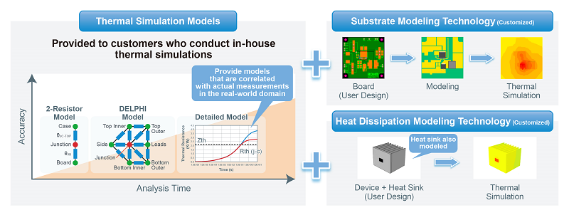
4) Thermal Simulation Models
In application circuits, issues such as a rise in load current due to faster CPU speeds and excessive heat generation resulting from greater miniaturization can be problematic. In fact, heat generation is one of the most important parameters as it affects component life. In addition, once a heating problem occurs, the number of procedures and man-hours required for rework can become overwhelming, entailing everything from component re-selection and board pattern modifications to a revision of the heat dissipation design.
ROHM provides a thermal dissipation simulation model that avoids these problems in advance, allowing users to carry out simulations using this model (Fig. 2). ROHM also possesses technology that enables modeling of substrates and heat dissipation fins, and can offer improvement proposals along with expertise in thermal designs based on user needs.
5) Evaluation Kits
ROHM offers evaluation kits (EVKs) that allow users to immediately begin evaluation in their circuit designs. After performing validation through simulation, we can provide an environment that can be verified on the actual device. Evaluation kits typically consist of an evaluation board, parts list, board CAD data, and thermal + noise evaluation data that can be used as a reference for component selection and board pattern design. Some evaluation kits can be purchased from online distributors.
6) PCB Library
Also a PCB library for CAD tools required by users for creating boards will be released.
Placing parts in the CAD tool requires component data (package information and mounting land pattern). To facilitate this, ROHM plans on offering PCB libraries for each part that users will be able to download and import into their CAD tool to complete product registration, simplifying board pattern design and circuit entry utilizing ROHM parts. It is provided as a standard BXL file, which can be converted based on the user’s CAD tool. (Free conversion tools are available)
7) Evaluation Support for User Boards
ROHM provides device-specific evaluation data as application notes to support evaluation on user boards. Comparing waveforms obtained from the board makes it possible to ensure that the device characteristics are correct. At the same time, key products listed on ROHM’s official website are readily available.
In addition, ROHM has formulated environments capable of measuring both heat generation and EMC not only on ROHM’s evaluation board but user boards as well (Fig. 3). Although design information is required, it is possible to perform EMC and thermal measurements on the user’s actual board, ensuring the reproducibility of characteristics that supports user evaluation.
Cutting-Edge Web Simulation Tool Capable of Complete Circuit Verification of Power Devices and ICs
In addition to the various support tools and environments described above, as part of a solution for solving user issues, ROHM launched a breakthrough web simulation tool on its official website in February 2020 called “ROHM Solution Simulator” that allows system and circuit board designers in the automotive and industrial equipment fields to perform complete verification of power devices along with the driver and power supply ICs utilizing solution circuits. (Fig. 4) This allows users with an Internet connection to immediately begin simulation of solution circuits provided by ROHM that combine power devices and driver ICs.
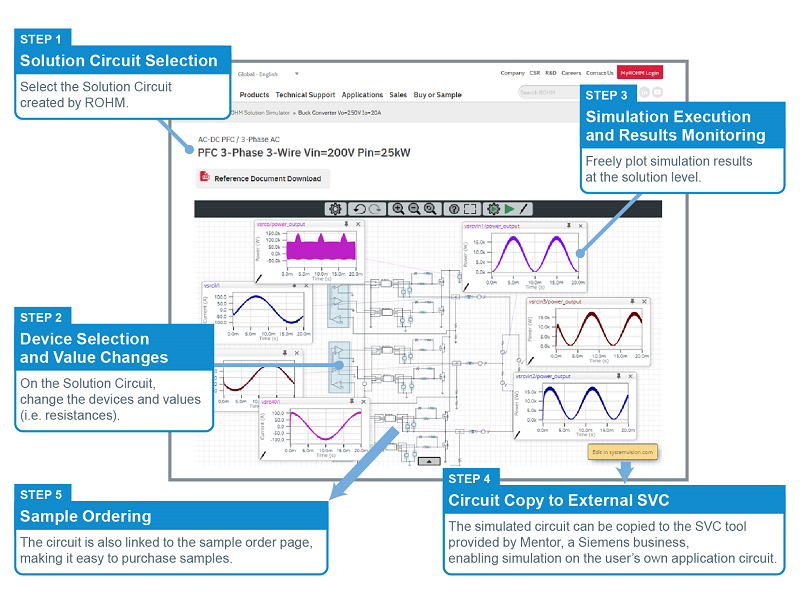
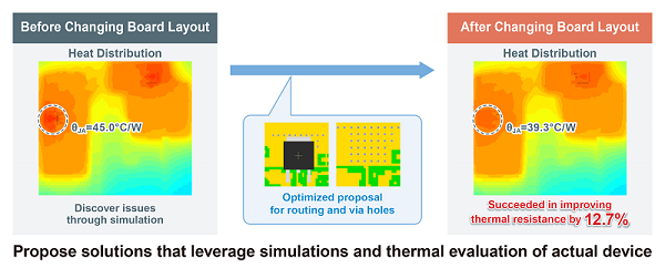
Using this simulator saves designers from the trouble of component selection, circuit creation, and configuring simulation models, making it possible to immediately start technical considerations. A broad range of products is available, from solution circuits that combine SiC power devices and driver ICs to power supply IC circuits integrating peripheral components, allowing a variety of simulations to be carried out, from initial development that includes the component selection and individual device verification to the system-level validation phase. Performing simulation validation helps identify trouble spots in the power supply circuit and provides the opportunity to remove defective components before ordering boards, significantly reducing application development effort (Fig. 5).
ROHM Solution Simulator was developed using the simulation platform SystemVisionTM Cloud (hereafter SVC) from Mentor, a Siemens Business. SVC is a cloud-based software service (SaaS) provided by Mentor that allows users to perform the latest multi-domain simulations. Supporting access from a web browser makes it possible to carry out analysis anytime, anywhere on a PC. In addition, circuits simulated by ROHM Solution Simulator can be exported and taken over, allowing user circuits to be added to perform simulations close to actual conditions. Importing the system to Mentor’s PCB board design environment (Xpedition series) enables seamless data transfer from component selection and circuit design to PCB board layout, minimizing user efforts. (Use of SVC requires registration of an SVC account – free of charge.)
ROHM Solutions Simulator Page: https://www.rohm.com/solution-simulator
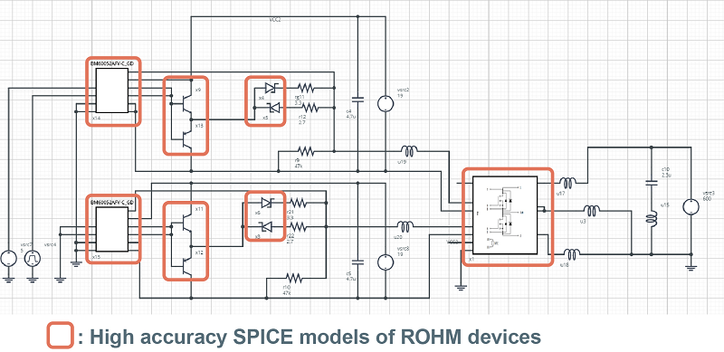
1) Devices (Fig. 6) and simulation circuit (Fig. 7)
・ SiC Power Module (BSM600D12P3G001)
・ SiC Power Module EVK (BSMGD3G12D24-EVK001)
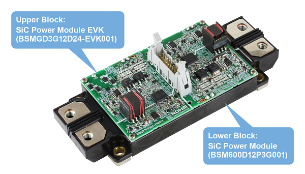
ROHM provides high accuracy SPICE models for each device, and the simulation circuit shown in Fig. 7 utilizes SPICE models of both the BSM600D12P3G001 and gate driver IC. Buffer circuits use the same format as BSMGD3G12D24-EVK001, and SPICE models for the transistors and diodes are also imported. In addition, adding parasitic inductances generated in the board and module allows for more accurate simulations to be performed.
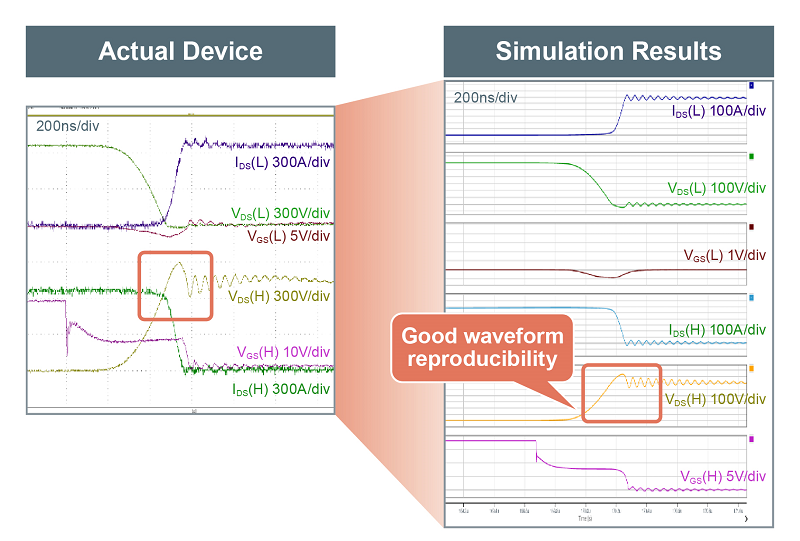
2) Simulation Circuit Results
Ringing along with undershoot can be reproduced during simulations, ensuring that the waveforms are close to the measurement results of the actual device. (Fig. 8)
3) Conclusion
To improve simulation precision, in addition to high accuracy SPICE models, it is necessary to consider the parasitic components that may be generated on the substrate. In the future, ROHM will continue to provide solution circuits incorporating parasitic component parameters (i.e. substrate, modules) that can occur during board design from the circuit design phase, allowing users to perform simulations closer to the actual results.
Evaluation Kits that Solves User Issues
Actual evaluation is critical to the user’s design flow. For some solution circuits registered for ROHM Solution Simulator, ROHM can provide a Solution EVK (Evaluation Kit) that facilitates verification of the simulated circuit on the actual device, enabling confirmation of the design validity in both the simulation and actual equipment. Doing so will help prevent problems that occur during design.
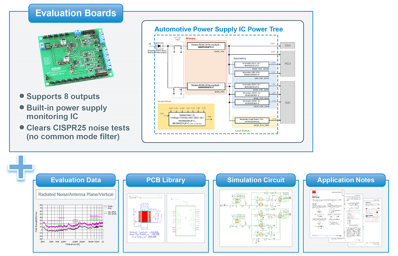
The first offering is a power tree board for automotive power supply ICs (Fig. 9) that drives power supply ICs using a configuration optimized for power systems required in automotive applications such as ADAS and cluster blocks. Assuming power supplies for SoC, MCU, CAN, etc., a primary DC/DC converter (BD9P series) that can connect directly to 12V batteries, DC/DC converter (BD9S series) used as a secondary power supply, linear regulator (LDO), and load switches are built-in. Also included are a reverse connection prevention diode and voltage monitoring IC (BD390xx series) that provide protection and functional safety.
In addition, the entire board has cleared CISPR25 Class 5 noise testing (a universal EMC test standard). ROHM has also implemented noise evaluation and can provide not only basic characteristics but also evaluation data on EMC noise and thermal data required as a set in application notes. Simulations allow users to select the optimum ROHM solutions with confidence.
Currently, we are developing SiC power device and gate driver evaluation boards, and plan to supply simulation and evaluation kits in the future as well.
Conclusion
ROHM provides support and tools from a variety of aspects as complete solutions designed to quickly solve user issues. (Fig. 10)
We believe that we can help prevent problems and failures while accelerating application development by proposing solutions optimized for each flow, from component selection to simulation, evaluation, and board creation.
In the future, ROHM will expand its library of solution circuits that maximize device characteristics and products compatible with ROHM Solution Simulator, along with Solution EVKs (Evaluation Kits) capable of verifying simulated circuits as-is, significantly reducing application development load and facilitating evaluation.
And, ROHM will continue to promote model development that couples electrical and thermal simulations while providing support that follows the flow of design methods utilizing simulations for application design in the automotive and other sectors, contributing to resolving customer issues.


