Exposure to vibrational forces can have a huge detrimental influence on the operation of equipment. It can shorten the working lifespan of such equipment through the loosening of fixings, the interruption of connections, or the direct damage to constituent components. It is possible to mitigate their effect on mechanical elements by locking them down with additional fixings or by deliberate isolation of sensitive areas via use of anti-vibration mountings. For electronic elements, however, things can prove a lot more difficult.
An electronic system can comprise a multitude of different components that might be susceptible to damage through being subject to heavy vibrations. There are numerous application settings where this can potentially happen – including those where electronics hardware is in close proximity to industrial drives, aircraft engines, etc.
Automobiles present an environment where vibrational challenges are commonplace, yet the critical nature of the functions that electronic systems need to provide here means that continued reliability cannot be compromised on – otherwise the safety of vehicle occupants or other road users could be jeopardized. The tried and tested methods employed within the avionics sector are not applicable in automotive designs, as these are complex and expensive. Alternative solutions are needed which are better aligned with the cost-sensitive, high-volume production requirements of the automotive industry.
Ensuring vibrational robustness
In order to make certain that electronic components have adequate resilience to vibrations, it is first necessary to establish benchmarks that should subsequently be conformed to. Though in an industrial application, the source from which the vibrations are being generated might be relatively easy to determine (such as a large scale drive), for an automobile there will be many different prospective sources from which the vibrations being experienced could emanate. Automotive manufacturers must therefore undertake comprehensive testing of their vehicle models.
It should be noted though that random vibrations cannot be standardised. A common technique is therefore to apply sinusoidal excitation, where the device under test (DUT) will be exposed to a series of different vibrational frequencies over the course of the test procedure, with their mechanical resonances being monitored. If a specific area is identified as being of concern then the vibrational input will remain focussed on that frequency for a longer period to see if component failure results. The internationally respected IEC 60068-2-6: 2008 standard subjects DUTs to cyclic sweeps across a predefined range of vibrational frequencies over a prolonged length of time. These frequencies can be set arbitrarily, but in most cases they will go from 10Hz to 150Hz, with 1g vibrational forces being applied. If components are intended for space deployment, then sweeps extending up to 2MHz may be conducted (so as to ascertain whether these components will be able to cope with the vibrations that will be undergone at launch).
Vibrational testing and the mathematics behind it
How acute a sinusoidal vibration is may be expressed in three different ways. These are as follows.
- The maximum amplitude/displacement.
- The maximum velocity – which occurs when the sinusoidal waveform crosses the zero displacement point.
- The maximum acceleration – which occurs at the peak of the waveform (as it is changing direction).

The logarithmic graph depicted in Figure 1 shows the relationship between the three quantities across different frequencies. This is based on velocity being the differential of displacement with time, and acceleration being the differential of velocity with time. Since the differential of sine is cosine, it represents a 90° phase shift. A further differentiation leads to an additional 90° phase shift.
The three lines plotted in Figure 1 are each equivalent to one another, so any of them could be used when defining the vibration intensity at a given frequency. It is convenient to quote a constant quantity, but testing limitations make it favourable to cite vibration intensity in reference to constant displacement at lower frequencies, then constant acceleration at higher frequencies.
Safeguarding capacitors against the threat of vibrational damage
Capacitors are a vital part of any electronic circuit – enabling electrical energy to be stored and released as and when it is required. They can serve a number of different purposes – such as energising devices, helping with the smoothing of voltage ripples on a supply to make it more stable, or enabling the filtering of noise from signals to enhance their integrity. Unfortunately, these components are among the most susceptible to vibrational problems. This is especially true for high value electrolytic capacitors. Through-hole leaded type electrolytic capacitors are often only capable of coping with a maximum of 10g and 1.5mm peak-to-peak displacement over a 10Hz to 55Hz frequency sweep. Although this may be good enough for non-critical commercial equipment, for automobiles, agricultural equipment and construction vehicles there is no doubt that elevated ratings are going to be mandated.
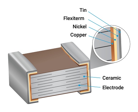
There are multi-layer ceramic capacitors (MLCCs) available from Kyocera AVX that are optimised for implementation in environments where high levels of vibration are expected. Its Flexiterm series benefits from an innovative design in which component integrity and operational reliability are maintained thanks to the flexible terminations that these MLCCs possess. Fracturing that might otherwise occur between the ceramic material and the corresponding termination surfaces (leading to the prospect of moisture ingress that will irrevocably harm the capacitor) is prevented in situations where there are heavy vibrations to contend with. This is done through the additional layer incorporated into these terminations. The layer (which is composed of a conductive polymer that has been plated with nickel and tin deposits) acts as an invaluable buffer to the stresses that flexing of the PCB to which the MLCCs are mounted will cause, providing supplementary mechanical pliability. Inclusion of this feature has been achieved while still keeping the unit costs involved low.

Flexiterm MLCCs can be supplied in capacitance values that range from 220pF to 100nF and case sizes from 0805 through to 2225. Among the application scenarios in which these components may be utilised are automotive (with the series having full AEC-Q200 qualification), wireless infrastructure, industrial automation systems and instrumentation.
KEMET has tackled the issue of vibration resilience in capacitors through the development of its FT-CAP MLCCs. Here a conductive silver epoxy is placed between the base metal and nickel barrier layers of the company’s standard termination arrangement. This allows terminal strength to be maintained and has no impact on electrical performance, but gives the flexibility needed to prevent cracks appearing during PCB flexure. These components have DC voltage ratings reaching 250V. They come in 0603 to 2225 case formats, covering capacitances of 180pF to 22μF (with ±5%, ±10% and ±20% tolerance margins). Key markets for these MLCCs include industrial, automotive, avionics, telecommunications, etc.

Conclusion
There are a growing number of use cases where the ability to withstand intense vibrations is a very high priority. Through the leveraging of proprietary technology, the leading capacitor manufacturers are now producing components that exhibit such attributes – assuring long-term operational reliability in even the most uncompromising of environments, while still being placed at attractive price points. TME recognises the importance of such ingenuity, and works with these companies to build the supply channels needed to support customers looking to source vibration resilient capacitors.


