The acronym for Pulse Width Modulation is PWM (Pulse Width Modulation). In power electronics, rectification and inverters are most frequently used. This calls for both an inverter bridge and a rectifier bridge. Three-phase power requires three bridge arms.
Using two levels as an example, each bridge arm has two power electronics, such as IGBTs. If the two IGBTs are turned on at the same time, a short circuit will happen.
The upper and lower devices won’t turn on at the same time by using a Pulse Width Modulation wave with dead time as a result. In other words, if one device is turned on, used for a while, and then turned off, the other can be turned on.
Definition of dead band
High-power motors, frequency converters, and other devices frequently use H-bridges or three-phase bridges made of high-power tubes, IGBTs, and other parts, according to easybom.
Although the upper and lower half bridges of each bridge can never be turned on simultaneously, there is frequently a delay effect when the high-speed Pulse Width Modulation drive signal reaches the control pole of the power element for a variety of reasons. As a result, one of the half-bridge components does not turn off when it should, which leads to the power components burning out.
The dead band occurs when the upper half bridge is turned off and the lower half bridge is switched on after a length of time, or when the upper half bridge is turned on after the lower half bridge has been turned off, to prevent burning the power components. The period of delay is known as the dead band. (Or, the components of the upper and lower part of the bridge are off.) PWMs with single-chip microcomputers at the low end lack dead time control.
A protection period is established when the Pulse Width Modulation is output to stop an H-bridge or half-H-upper bridge’s and lower tubes from turning on simultaneously because of a switching speed issue. As a result, the output from the top and lower tubes won’t be available right once. Obviously. Although the waveform output will be stopped, very little of the cycle will be dead.
Because the PWM wave itself has a very low duty cycle and the vacant part is larger than the dead band, the dead band will have an impact on the output ripple but shouldn’t be particularly significant.
DSP dead time with Pulse Width Modulation
During the rectification and inversion process, the upper and lower bridges of the same phase cannot be turned on at the same time as the power supply will short-circuit. The device’s goal is to stop the PWM from being an abrupt level jump, even though the DSP’s Pulse Width Modulation won’t theoretically turn on at the same time. The higher and lower bridges may pass through the trapezoidal shape that it constantly assumes. In order to prevent a direct link between the upper and lower bridges, the higher and lower bridges are consequently briefly closed and then selectively turned on. Real-time control performance will change as a result of the dead band. Difference.
It is not possible to turn on both the top and lower bridge arms of the Pulse Width Modulation at the same time. A short circuit will happen if the power supply’s two ends are turned on simultaneously. As a result, after a predetermined period of time, the two triggering signals must disconnect the triode. This area is referred to as the “dead band.”
The PWM’s duty cycle, which does not control current, determines the average voltage output to the DC motor.
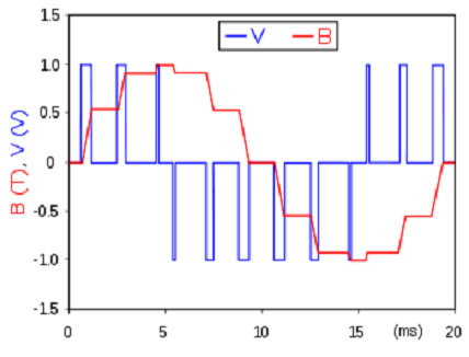
PWM, which stands for Pulse Width Modulation, is the process of varying the interval between the high and low values of a square wave. In contrast to a 20% duty cycle waveform, which has 80% low level time and 20% high level time, a 20% duty cycle waveform has 20% high level time. The waveform has a 60% duty cycle with 40% low level time and 60% high level time. The output pulse’s amplitude, also known as the voltage, duty cycle, and high level period, all increase with increasing output pulse amplitude.
No voltage is output if the duty cycle is 0% and the high time is also 0%.
The entire voltage is output when the duty cycle is set to 100%.
Therefore, the goal of altering the output voltage may be realized and the output voltage can be continuously and steplessly modified by adjusting the duty cycle.
Topics related to Pulse Width Modulation
1. Duty cycle
It is the proportion between the amount of time the output PWM’s high level is maintained and the length of the PWM’s clock cycle.
For instance, a PWM’s clock cycle is 1ms, or 1000us, if its frequency is 1000Hz. If the high level is visible for 200us and the low level is visible for 800us, the duty cycle is 200:1000, or 1:5.
2. Resolution
Therefore, it is possible to complete the minimal duty cycle. For instance, 8-bit PWM has a theoretical resolution of 1:255 (single slope), whereas 16-bit PWM has a theoretical resolution of 1:65535. (single slope).
This is how frequently it occurs. For instance, 16-bit PWM has a resolution of 1:65535. To get to this conclusion, T/C must be counted from 0 to 65535. From 0 to 80, count backwards from 0…. As a result, it has a minimum resolution of 1:80 and is faster, which suggests a higher PWM output frequency.
3. Double slope / single slope
Think about a PWM that counts up to 80, then back down to 0, then back up to 80. Here, there is only one slope.
Think of a PWM that counts from 0 to 80 before returning to 0. A double inclination exists here.
The output PWM frequency is halved due to a doubled double slope counting time, but the resolution is doubled to 1: (80+80)=1:160.
The microcontroller will decide whether an individual IO port outputs 1 or 0 or is reversed in accordance with your settings when T/C counts from 0 to 10 (the counter continues to count up until it reaches the set value of 80). Assuming that the PWM is a single slope, set the highest count to 80 and a comparison value of 10. In this way, it is the most essential Pulse Width Modulation principle.


