


- Abstract
Power products are widely used in all kinds of household appliances and vehicles in our daily life. They are also widely used in aerospace and other special industries.
In order to reduce the interference received during the stable operation of the power supply, it is necessary to connect capacitors in parallel on the input side of the power supply. At the same time, fuses or circuit breakers are connected in series on the input side to realize the input overload protection of the power equipment. Due to the existence of input capacitance, a large input impulse current will be generated during the startup of a power supply device, which may result in the fuse or circuit breaker being blown. This paper introduces the design and application of the inrush current suppression scheme of power supply equipment and provides reliable solutions.
- Causes of Input Inrush Current
The generation path of input inrush current is shown in Figure 1.
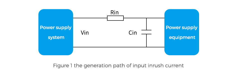
The input voltage(Vin) rises rapidly and charges the input equivalent larger capacitor(Cin) via the input equivalent impedance(Rin) when the power supply system starts up.
When the input circuit without the input inrush suppression circuit, Rin is mainly the PCB alignment impedance, the common mode/differential mode inductance in the EMC circuit, and the interface connection impedance, etc. The Rin is relatively small (negligible compared to the impedance of the input inrush circuit suppression circuit), which will result in a large input inrush current.
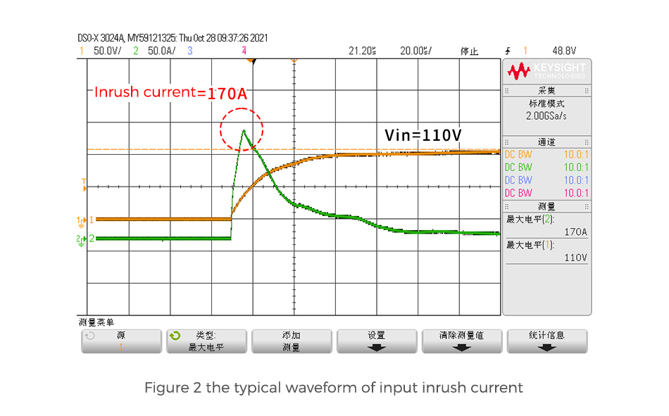
As shown in Figure 2, when Vin = 110VDC, Cin = 100uF, and there is no current suppression circuit, the input inrush current(Iin) will reach 170A.
- Application Diagram of Input Inrush Current Suppression Circuit
Application diagram of input inrush current suppression circuit is shown in Figure 3.
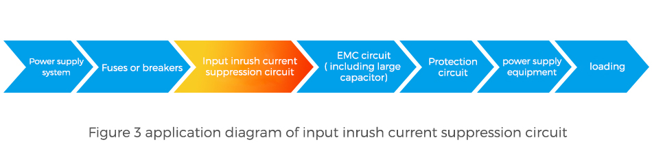
High input inrush current will cause the fuse or circuit breaker on the input side to blow. Input inrush current suppression is essential, especially for applications with high reliability requirements.
- Comparison Between Circuit Schemes
In order to effectively suppress the input inrush current, the following schemes are often adopted in the power supply industry:
Scheme 1: Connect the resistor (R1) in series in the input circuit of the power supply equipment to suppress the input inrush current, as shown in Figure 4.
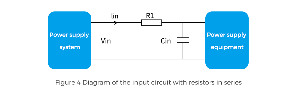
When the power supply starts working, the voltage of the input capacitance(Cin) is small and the maximum input inrush current is . In order to effectively suppress the input inrush current, the resistor(R1) in series must have a large resistance value. However, when the power supply is working stably, a continuous current flows through R1, R1 will heat up seriously and reduce the efficiency of the product.
For example, Vin = 110VDC, output power(Po) = 100W, efficiency(ƞ) = 93%, the required input inrush current(Iin) ≤ 10A, the resistor(R1) can be , the input current of R1 is , and the loss of R1 is . Taking into account the size and temperature rise of the resistor, the pR1 is generally required to be less than 1W. According to the previous calculation formula for the inverse, only power supply equipment that are less than 30W are applicable to this scheme, other power supplies that are more than 30W need to use a more optimal scheme.
Scheme 2: Connect the NTC thermistor(RT) in series in the input circuit of the power supply section to suppress the input inrush current, as shown in Figure 5.
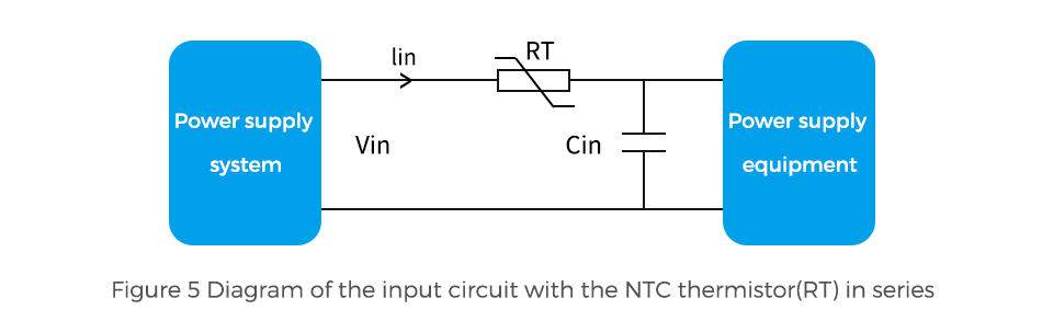
The thermistor solution can solve the problem of severe heat generation and efficiency degradation caused by the resistors in Scheme 1.
When the power supply equipment is just starting up, the thermistor is not hot, the resistance value is large, which can suppress the input inrush current. After steady operation, the resistance value decreases, and the thermistor generates little heat and has little effect on the product efficiency.
The scheme 2 has the advantages of less heat generation and less impact on product efficiency. However, due to the characteristics of NTC thermistors, the resistance decreases as the temperature increase and the resistance recovery time is long. The disadvantages of this scheme are as follows:
(1) When starting in a high temperature environment, the resistance of the thermistor is small, which cannot suppress the input inrush current well;
(2) When starting in a low temperature environment, the resistance of the thermistor is large, which may cause the poor starting;
(3) When starting in a short switching interval, the resistance of the thermistor has not recovered to a large resistance value after a reduction in steady-state, which cannot suppress the input inrush current well.
Scheme 3: Connect resistor(R1) in parallel with the electronic switch(S1) and then connected in series in the input circuit of the power supply equipment, and the automatic control circuit is used to control whether the S1 is connected to circuit to suppress the input inrush current, as show as Figure 6.
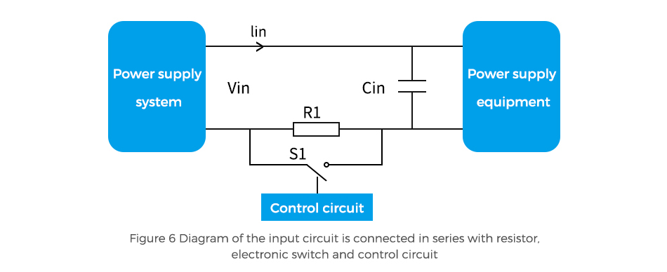
Scheme 3 can overcomes the disadvantages of scheme 1 and scheme 2. During start-up, the electronic switch(S1) is disconnected, the resistor(R1) suppresses the input inrush current and the electronic switch S1 is connected during steady-state operation.
The advantages of scheme 3 are as follows:
(1) It can effectively suppress the input inrush current. In addition, the R1, the S1 and the control circuit are less affected by temperature and the input inrush current suppression effect is less affected by temperature.
(2) The resistor and electronic switch have low loss and heat generation, which has little effect on power supply efficiency.
(3) The control circuit can be quickly restored and can also effectively suppress the input inrush current even if the power supply equipment switching interval is short.
Scheme 4: Connect the electronic switch(S1) in series in the input circuit of the power supply equipment, and use the automatic control circuit to control the impedance of the S1 for constant current control of the input inrush current, as shown in Figure 7.
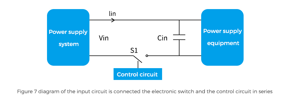
To overcome the disadvantages of Scheme 1 and Scheme 2, Scheme 4 can also be adopted. Besides the advantages of Scheme 3, Scheme 4 has the following advantages
(1) Without the resistor R1, the size and cost of the equipment can be reduced.
(2) The impedance of the electronic switch adopts constant current control, which is less affected by the input voltage variation.
In summary, Scheme 3 or Scheme 4 can be selected for applications requiring high performance and reliability.
- Reliability Design of Power Supply Equipment
Power supplies need to be designed to achieve high reliability. They are subject to environmental influences (such as cooling, dry heat, alternating hot and humid, vibration, shock, etc.), EMC influences (conducted CE, RE, EFT, overvoltage, surges, ESD, etc.) and other influencing conditions, so power supplies are designed to meet these application specifications in terms of circuit characteristics and lifetime, etc.
The reliability of power supply equipment is mainly considered from the following three aspects:
(1) Design reliability: circuit selection, derating design, thermal design, safety design, EMC design and PCB design;
(2) Raw material reliability: selection of materials according to reliability specifications such as failure rate, MTBF and lifetime;
(3) Manufacturing reliability: manufacturability, manufacturing environment and manufacturing personnel.
- Application Scheme of Power Supply Equipment
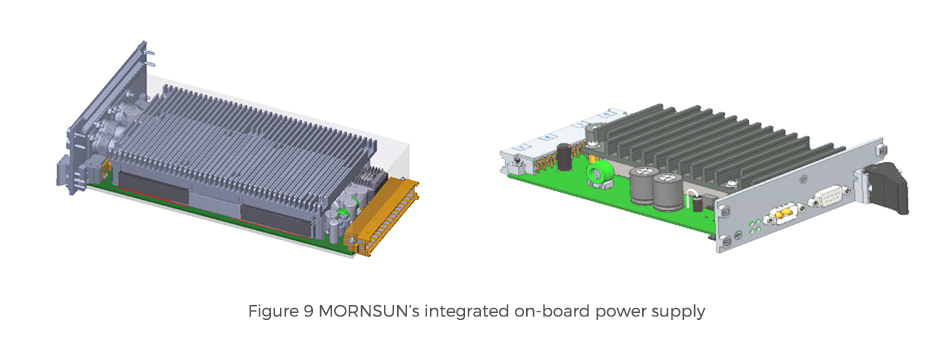
As an example, the MORNSUN power supply module is applied to the electrical traction control unit of a railway system, as shown in Figure 8.
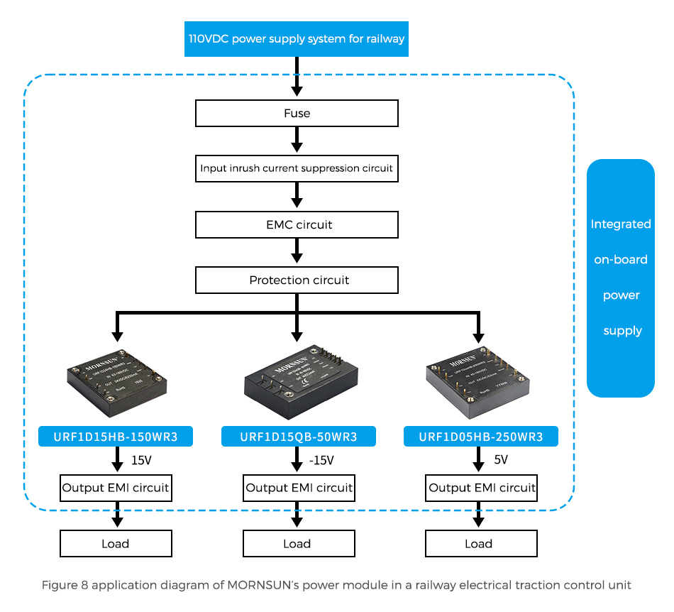
The 110VDC railway power supply system is adopted to supply power to the MORNSUN DC/DC power supply modules through the input inrush current suppression circuit, protection circuit and EMC circuit. The DC/DC power supply modules convert the voltage into three different output voltages, and then supply power to different loads through the output EMI circuit.
The on-board power supply integrates input inrush current suppression circuit, EMC circuit and protection circuit (against reverse connection, over-voltage, under-voltage, over-current, short-circuit, etc.). This integrated on-board power supply meets the railway standard EN50155 and its output inrush current is less than 10A (Shown in Figure 9).
- Conclusion
Power supply equipment is widely used in various industries and the threat of input inrush current is omnipresent, especially for power supply equipment with high reliability requirements, it is essential to design input inrush current suppression circuit. MORNSUN provides customers with one-stop solutions of power supply, we can also provide tailored integrated power supply for applications in railway and other industries to better meet customers’ application needs and simplify product development and test cycle, comprehensively improve the stability, safety and reliability of the customer system.
For more information, please visit www.mornsun-power.com


