As automotive radars become more widespread, the heavily occupied RF spectrum will resemble an electronic battlefield in an urban environment. Radar will face a combination of unintentional or intentional jamming attacks, and designers must implement counter-jamming techniques like ones used in electronic warfare (EW).
An automotive radar could typically experience a denial or deceptive jamming attack. Denial jamming blinds the victim radar. This technique reduces the signal-to-noise ratio and, as a result, the probability of target detection is degraded. On the other hand, deceptive jamming makes victim radar “think” there are false targets. The victim radar loses the ability to track real targets and, hence, the victim’s vehicle behavior is severely influenced.
These jamming attacks could originate from mutual interference between automotive radars or happen deliberately by simply pointing a strong continuous wave (CW) signal into victim radar using inexpensive HW.
While current jamming avoidance techniques might be adequate for today, with the proliferation of radar sensors, a resilient type of mitigation techniques will need to be used by itself or in conjunction with the avoidance approaches. Resilient techniques include time frequency domain signal processing or complex radar waveforms.
Radar Waveforms
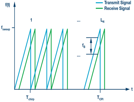
The radar waveform is one of the critical system parameters that determines the sensor performance in the presence of jammers. Automotive radars in today’s 77 GHz band mainly use FMCW type waveforms. In FMCW radar, a CW signal is linearly swept or chirped in frequency across an RF band. Figure 1 shows an example FMCW chirp sequence (CS) waveform.

The frequency difference (fb, beat frequency) is proportional to the distance R to the target and can be determined by the following relation:

Impacts of Jamming
Jamming occurs in a dense RF environment when FMCW radar sensors are operating in the same portion of the frequency band. See a typical oncoming automobile jamming example in Figure 2.

Denial Jamming
An arbitrary FMCW type strong jamming signal that falls into the receiver bandwidth raises the noise floor of the victim radar. This denial jamming may cause small targets (that is, small radar cross section (RCS)) to disappear due to the poor SNR.
A denial attack could also purposefully be carried out by simply beaming a strong CW signal into the victim FMCW radar. The impact in the victim radar would be similar to an FMCW jamming case (see Figure 4).
Deceptive Jamming
If the jamming signal sweep is synchronized but delayed with the victim radar, then the impact would be deceptive false target generation at a fixed range. Such techniques are common with EW jammers. An oncoming automobile radar of a similar type will act as an unintentional jammer. However, the probability of time alignment, between victim and jamming radar, would be very small. A jammer delay offset that is less than the maximum range delay of the victim radar could look like a real target. For example, a 200 m max range would require sweep alignment of less than 1.3 μsec. However, such a deceptive attack could be carried out intentionally using sophisticated EW-like equipment mounted on the oncoming automobile platform.
More generally, deceptive jamming is based on retransmitting the victim radar’s signal with a systematic change in delay and frequency. This can be either noncoherent, in which case the jammer is called a transponder, or coherent, when it’s a repeater. Repeaters receive, alter, and retransmit one or more jamming signals, whereas transponders transmit a predetermined signal when a desired victim signal is detected by the jammer.
A sophisticated repeater-based attack would typically require a digital RF memory (DRFM). A DRFM is capable of carrying out coordinated range delay and Doppler gate pull off attacks. So, the false target range and Doppler properties are maintained to deceive the victim radar.
Jamming Mitigation Techniques
Basic Approach: Avoidance
Basic radar jamming mitigation techniques mostly rely on the avoidance approach. The objective is to reduce the probability of overlap in space, time, and frequency such as:
- Spatial: Use of narrow and electronically scanned beam can reduce jamming risk. A typical field of view for long range automotive cruise control (ACC) radar is ±8°. Nonetheless, a strong jammer could still be effective through the antenna side lobes.
- Temporal: Randomize FMCW chirp slope parameters to avoid periodic jamming.
- Spectral: Randomize FMCW chirp start and stop frequencies to reduce the probability of overlap and jamming.
The basic methods of randomization would avoid accidental synchronization with other radars, but might not be as useful in dense RF environments. The growing number of radar sensors will require more sophisticated resilience techniques to mitigate the jamming.
A Strategic Approach: Detect and Repair
An alternative method of avoidance could be used to repair the received waveform using signal processing algorithms. Time frequency domain techniques could be effective against the denial type of jamming attacks. In the oncoming automobile FMCW jamming scenario, the jammer sweeps all frequency bins for a very short duration of time. This fast time varying signal manifests itself as a raised noise floor in regular FFT domain. Time frequency domain signal processing technique transfers the signal to another domain where it is easier to filter out the jamming in comparison to FFT domain (see Figure 3).

For time varying signals, a short time Fourier transform (STFT) provides more information than a regular FFT. STFT-based techniques could be used for narrow-band jamming excision. The STFT essentially moves a window through the signal and takes the FFT of the windowed region. The signal is filtered in the frequency domain to remove the jammer components before being transformed back to the time domain.
Figure 4 shows a typical FMCW jamming scenario of overlapping RF chirp sequences along with resulting IF beat signal in the STFT domain.

The plots on the right of Figure 4 show the IF domain that is the end result of the mixing of radar (blue) and jamming (orange) signal. A horizontal line would indicate a target, whereas V shaped vertical lines indicate the presence of a jamming signal.
Similar or opposite direction jamming FMCW, or even a CW-like slow chirp, have similar impacts in the IF signal. In all of these jamming scenarios, the fast moving V shaped IF signal raises the noise floor in the regular FFT domain, as shown in Figure 3.
An amplitude-based masking could be used to filter out the jamming signal in the STFT domain. This assumes, of course, that the victim radar front end and quantization have enough dynamic range to process the stronger jammer signal and the small intended target linearly at the same time. See Figure 5.

The top image of Figure 5 depicts a strong jammer, while the bottom shows an STFT after processing. Multiple real targets are not visible in the presence of strong jammer, as in the top. The V shaped jammer in the lower plot is excised and the low SNR targets would now be discernable when transferred back to the time domain.
The STFT-based jamming mitigation technique could be used in denial jamming scenarios against strong jammers. For deceptive jamming attacks, an STFT alone cannot authenticate whether the return signal is real or false.
Encrypted RF
The elementary countermeasure to reduce the impact of deceptive jamming from repeater attacks is the use of low probability of intercept (LPI) radar waveforms. The objective of an LPI radar is to escape detection by spreading the radiated energy over a wide spectrum of frequencies, usually via quasi-random sweep, modulation, or hopping sequences. FMCW is a type of LPI waveform. If phase coding, or encryption, is introduced into the frequency chirp, it is possible to further reduce the chances of a DRFM intercepting the automotive radar signal.
An encrypted RF signature unique to each radar sensor could authenticate the return signal. Figure 6 shows a use case where two identical radars (one of which is mounted on a different automobile) with frequency offset and delay between them generates a false target in the victim radar. The jamming radar is time aligned (same chirp slope and a short offset) with the victim radar.

Phase coded FMCW radars could offer high jamming robustness in this use case. The use of orthogonal codes could also make MIMO radar operation possible by enabling multiple simultaneous transmit waveforms.
Requirements of coding:
- Code length: The goal is to achieve minimal range sidelobe levels with short sequences. A PRN sequence length of 1024 results in a peak side lobe level (PSLL) of about 30 dB (10log1024). Transmit codes together with the receive filter weights could be optimized to improve the PSLL at the expense of SNR.
- Good cross-correlation properties: Cross-correlation coefficients of the members of a set should be zero to achieve a good separation between sensors
- Doppler resistance: Phase coded radar performance could suffer from the Doppler shift. Binary codes are Doppler intolerant. Polyphase codes degrade less rapidly than binary codes.
- Available number of different codes: A large family size is better to assign a unique code to each radar sensor.
Figure 7 illustrates the radar echo with no phase coding. Jamming signal shows itself as a false target. When the transmitter FMCW waveform is phase coded with a PRN sequence, the jamming signal could be suppressed, as shown in Figure 8.


The dynamic range is compromised with this method. However, the radar signal processor could use phase coded FMCW for a few chirps to flag a false target and then switch back to normal operation.
Conclusion and Future Trends
Jamming in congested automobile radar sensor environments can be mitigated using advance signal processing algorithms and complex waveform generation techniques. STFT-based signal processing techniques could be used against denial type of attacks. Phase coded FMCW provides an additional layer of resistance to both noncoherent and coherent deceptive attacks by means of processing gain and interception avoidance. See Table 1 for the summary of mitigation techniques.
| Jamming Type | Denial | Deceptive | |
| Jamming HW | Another radar sensor or a simple CW generator | DRFM (coherent) | Transponder (noncoherent) |
| Impact on the victim radar | Poor SNR | False target | False target |
| Resilient mitigation technique | STFT | Phase coded FMCW | Phase coded FMCW |
| Mitigation principle | Repair the radar return waveform | Escape detection | Processing gain of the coding sequence |
| Mitigation effectiveness (expected) | High | Moderate | Good |
The previously detailed jamming mitigation principles for automotive radars are also applicable for other radar sensor environments—for example, robotics, road tolling, GPS, and UAV landing or collision avoidance systems.
Currently automotive radar sensors are operating in noncooperative mode without communicating with each other. Although a cooperative mode of operation would require industry-wide harmonization, the arbitration between radar sensors could help resolve the interference issue.
A future radar concept including the sensor cooperation would be the fusion of communication nodes and radar sensors. Future radars with complex waveforms offer the possibility to include information in the radar signal as well. The same HW could be used for radar and communications (RadCom) simultaneously.
RadCom: One Single System for Simultaneous Radar and Communications:
- Multi-user capability without interference
- The coding of the radar signal with OFDM or similar communication codes offers the possibility to include information in the radar signal
- Simultaneous due to OFDM-based radar transmit signals
5G millimeter wave transceiver signal solutions from ADI with greater than GHz bandwidth and beam steering capabilities could be a potential candidate for a RadCom system concept.
ADI is in a unique position to develop both state-of-the-art radar sensors and 5G millimeter wave solutions to pave the way for future RadCom systems.
Analog Devices Drive360 28 nm CMOS Radar Technology:
ADI’s Drive360™ 28 nm CMOS radar platform enables many high level signal processing integration options and even allows for custom IP integration enabling designers to differentiate their systems. A highly integrated power management companion chip accompanies the platform. This system brings Tier 1 and OEMs the high performance required to build robust solutions for emerging autonomous driving applications.
5G Millimeter Wave
Analog Devices brings a strong contribution to the 5G microwave effort with our unique bits to microwave capability. Our broad technology portfolio and continued RF technology advances combined with our rich history in radio systems engineering put ADI in a leading position to pioneer new solutions for our customers at microwave and millimeter wave frequencies for the emerging 5G systems.


