

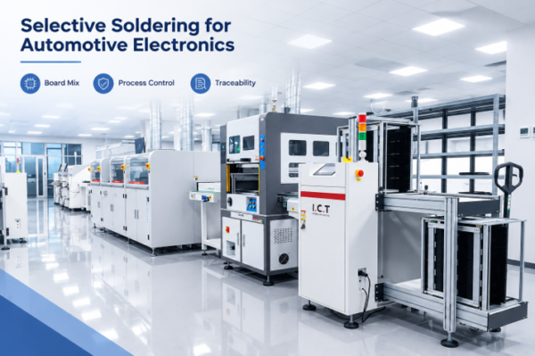
Choosing a selective soldering machine for automotive electronics begins with the assemblies you must build, not with a brochure specification. The correct machine must reach every required through-hole joint, deliver a stable thermal process across high-mass and heat-sensitive parts, record the variables your quality system needs, and support the takt time and changeover pattern of the line. A machine that looks fast in a standard demonstration can still create risk if its nozzle cannot access a connector, its preheat cannot control a heavy ground plane, or its software cannot protect approved recipes.
The most reliable selection process converts product requirements into a measurable acceptance plan. Start with representative boards, identify the difficult joints, define the process window, and then compare machine architecture, controls, traceability, maintenance, and supplier support against that plan. This approach makes the purchase decision easier to defend and reduces the chance of discovering a process limitation after installation.
Start With the Automotive Assembly
Automotive control units, power modules, sensor interfaces, lighting electronics, and body-control assemblies can place very different demands on selective soldering. Some boards contain only a few pin headers. Others combine large connectors, relays, transformers, shields, and thick copper areas on the same assembly. The machine must handle the actual mix of pin lengths, component heights, board thicknesses, pallet designs, copper distribution, and keep-out zones.
Map the difficult joints
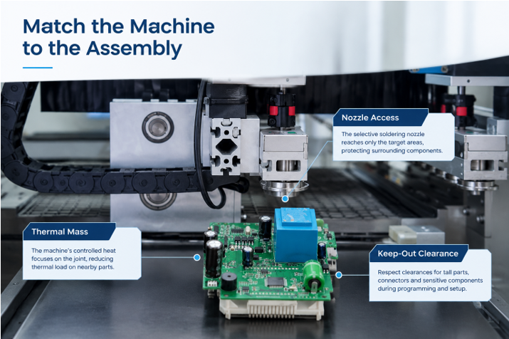
Create a bottom-side map for each candidate board and mark the joints that are closest to surface-mount parts, plastic housings, board edges, tooling features, or tall neighboring components. Record the available nozzle approach area and the distance between the target joint and anything that must remain outside the solder wave. A small nozzle may improve access, but it can also deliver less heat and may require slower motion or more preheat. A larger nozzle may improve heat transfer, but only if the surrounding clearance allows it.
Thermal mass deserves the same attention. Ground pins connected to large copper planes, power terminals, and metal-bodied connectors may need more energy than signal pins. The selection team should identify these features before the demonstration so the supplier can prove that the machine reaches acceptable barrel fill and wetting without overheating the laminate or nearby components.
Define quality and data requirements
Automotive programs usually require disciplined process control, documented change management, and traceability that can support internal rules and customer-specific requirements. Decide which data must be stored for every board, batch, or recipe. Typical items include product ID, recipe version, operator or user level, flux settings, preheat values, solder-pot temperature, alarm history, cycle result, and timestamps. If the factory uses a barcode system or MES, confirm the communication method and the exact data handshake before purchase.
Define the Process Window Before Comparing Machines
Selective soldering normally combines flux application, preheating, and localized soldering. The machine must control all three stages as one repeatable process. A strong equipment comparison therefore uses a process window rather than one nominal cycle. Ask the supplier to demonstrate the lowest and highest practical limits for the boards you intend to run, including cold-start conditions and continuous production after the solder system has reached equilibrium.
Flux application and preheat
Flux must reach the intended area consistently without contaminating connectors, test points, or surfaces that require cleanliness. Evaluate spray accuracy, dot size, monitoring, refill method, extraction, and access for cleaning. For preheat, compare the available technology and zoning with the board construction. The goal is not simply to raise the board temperature. It is to prepare the joint for soldering, reduce thermal shock, support flux activation, and keep sensitive components within their allowable exposure.
During trials, measure board temperature at representative locations rather than relying only on the machine setpoint. Include a high-mass joint, a thermally sensitive area, and a typical joint. The recorded profile should remain repeatable across several boards and after normal pauses in production.
Nozzle access and solder contact
Nozzle choice affects access, heat transfer, wave stability, cycle time, and maintenance. Review the available nozzle diameters and shapes, the minimum practical clearance, the ease of changing and aligning nozzles, and the method used to maintain wave height. Where the product mix is broad, the value of a flexible nozzle library may be greater than a small difference in nominal machine speed.
Choose the Right Machine Architecture
Offline or inline operation
An offline system can be a good fit for lower volumes, engineering builds, repair work, or factories where an operator can load and unload boards without interrupting the wider line. An inline machine becomes more attractive when takt time, automated handling, line balancing, and board-level traceability are central requirements. The decision should include upstream and downstream buffers, conveyor height and direction, pallet return, barcode reading, and the recovery plan when one station stops.
When comparing an automatic selective soldering machine with an operator-loaded configuration, calculate labor and handling around the complete shift. Automation only creates value when board identification, transfer, recipe selection, fault recovery, and maintenance access work as one production system.
Single or parallel soldering capacity
A single soldering unit offers a simple process path and may provide enough capacity for boards with a limited number of joints. Parallel or multiple soldering modules can increase throughput when products contain many joints or when the line must support a short takt time. However, capacity should be demonstrated with the real joint pattern. Travel distance, fluxing, preheat, board transfer, vision alignment, and tool-change time all contribute to the cycle. Ask for a time study that separates each element rather than accepting a headline cycle-time estimate.
Board handling and changeover
Confirm the supported board dimensions, weight, warpage, edge clearance, and pallet requirements. If several automotive programs will share the machine, test the recipe-change process and physical changeover. Operators should be able to select the correct program without bypassing approvals, and fixtures should locate the board repeatably while allowing access to the target joints. Look for poka-yoke features that prevent the wrong pallet, nozzle, or recipe from being used.
Evaluate Process Control and Traceability
Control the variables that change joint quality
The control system should make critical parameters visible, repeatable, and difficult to change accidentally. Review how the machine monitors flux pressure or flow, preheat output, solder temperature, solder level, wave or pump behavior, nozzle condition, axis position, and nitrogen conditions if nitrogen is used. Confirm how alarms are generated, whether production stops on a critical deviation, and whether the event is recorded. Camera or fiducial alignment should also be tested on the real board and pallet, including expected variation in board position.
Protect recipes and production records
Recipe management is especially important when one machine serves several vehicle platforms or part numbers. The software should support user permissions, controlled recipe release, revision history, backups, and restoration. Verify what happens when the barcode does not match the active program, when communication with the MES is lost, or when a parameter is outside its approved range. A useful traceability system records the information needed to investigate a defect without creating an impractical volume of unusable data.
Plan maintenance and contamination control
Selective soldering performance depends on clean flux delivery, stable solder flow, healthy pumps, undamaged nozzles, accurate sensors, and controlled dross. Inspect access to the fluxer, filters, solder pot, pump, nozzles, preheaters, conveyors, and extraction path. Ask the supplier to demonstrate daily cleaning, nozzle change, solder-pot service, calibration, and recovery from common faults. Spare parts, consumables, training, remote support, and local response time should be included in the commercial comparison.
Run a Product Specific Acceptance Test
A product-specific trial is the strongest evidence that a machine fits the application. Use production-intent boards, components, solder alloy, flux, pallets, and process constraints whenever possible. The test should include a normal board and the worst credible combination of thermal mass, nozzle clearance, pin length, and joint count. Run enough consecutive boards to reveal drift, warming effects, replenishment issues, and changeover errors.
Agree on measurable acceptance criteria
Define inspection and acceptance methods before the trial. Depending on the product and quality plan, these may include visual inspection, X-ray where it adds value, barrel-fill assessment, wetting evidence, bridge and icicle checks, flux-residue review, thermal profiling, pull or functional tests, and cross-section analysis for selected joints. Use the applicable workmanship standard and customer requirements, but do not let a general standard replace product-specific risk analysis.
The supplier should also demonstrate repeatability, recipe locking, alarm behavior, traceability output, and the promised changeover method. Record all machine settings used for accepted samples. Those settings become the starting point for installation qualification and prevent the factory acceptance test from becoming a one-time demonstration that cannot be reproduced later.
Questions to ask during the demonstration
- Which board or joint feature sets the practical limit for nozzle access?
- How is the process kept stable as solder level, dross, and nozzle condition change?
- Which parameters are monitored, logged, alarmed, and interlocked?
- How does the system verify the correct board, pallet, nozzle, and recipe?
- What maintenance tasks require production to stop, and how long do they normally take?
- Which spare parts and consumables should be held on site?
- What evidence will be provided at factory acceptance and site acceptance?
Compare Total Cost and Supplier Support
Purchase price is only one part of the decision. Compare the cost of fixtures, nozzles, flux consumption, solder management, nitrogen if required, extraction, preventive maintenance, calibration, spare parts, programming, training, and line integration. Also consider the cost of slow changeovers, false alarms, difficult cleaning, and poor access to service components. A less expensive machine can become costly if it needs frequent expert intervention or cannot adapt to the next product family.
Supplier capability matters because selective soldering is an application process, not only a piece of hardware. Evaluate the quality of the pre-sale process study, the clarity of the acceptance plan, software and electrical documentation, training materials, remote diagnostics, commissioning support, and the supplier’s willingness to test difficult boards. The best partner will explain the limits of the proposed configuration and show how those limits were tested.
Final Selection Checklist
- Representative boards and worst-case joints have been identified and tested.
- Nozzle access, keep-out clearance, and thermal mass are confirmed for every critical joint.
- Fluxing, preheat, and soldering controls produce a repeatable process window.
- Machine architecture meets takt time using a documented product-specific time study.
- Board handling, recipe selection, and changeover include error-proofing.
- Traceability, user permissions, alarms, backups, and MES communication are verified.
- Maintenance access, consumables, spare parts, training, and service response are acceptable.
- Factory and site acceptance criteria are written into the purchase agreement.
Conclusion
The right selective soldering machine is the one that proves it can build your automotive assemblies within a stable, documented, and maintainable process window. Begin with the board and the difficult joints, then evaluate architecture, capacity, controls, traceability, maintenance, and support against measurable acceptance criteria. This keeps the decision focused on production risk and long-term process capability rather than a short list of nominal specifications.
For a practical starting point when reviewing configurations, process options, and supplier support, visit I.C.T selective soldering and prepare a sample-board package that includes drawings, board data, expected volume, takt time, solder and flux requirements, traceability needs, and the joints you consider most difficult.