


Abstract
Thevenin and Norton equivalent of two different networks is obtained by using the Pspice simulation analysis program. The new networks have Thevenin(Norton) impedance which are product and numerical division of two different individual networks , Thevenin voltage (Norton current) which are numerical multiple and sum of the given Thevenin voltage (Norton current) of individual two networks.
I INTRODUCTION
SPICE/PSPICE methods to obtain Thevenin, Norton equivalent circuits for purely resistive and networks with R, L, C elements , and dependent sources are described [1-4] by the author previously. In this idea, a circuit method which is implemented by Pspice software, to obtain the following equivalent circuits is described.
- A Thevenin equivalent circuit whose, (i) open circuit voltage is the multiple of two open circuit voltages (two different circuits, a purely resistive with independent and dependent sources, and another consisting of resistive and independent sources),(ii) Thevenin impedance which is a negative multiple of two Thevenin impedances (two different circuits, again a purely resistive and independent/dependent sources, and another consisting of DC sources and resistive circuit elements).
- A Norton equivalent circuit whose, (i) short circuit current is the sum of two short circuit currents(two different circuits, a purely resistive, and another consisting of AC elements),(ii) Norton admittance which is a division of two Norton impedances (two different circuits, again a purely resistive with dependent and independent sources, and another consisting of AC circuit elements with dependent and independent AC sources ).
II THE CIRCUITS
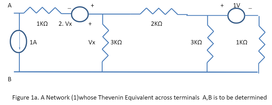
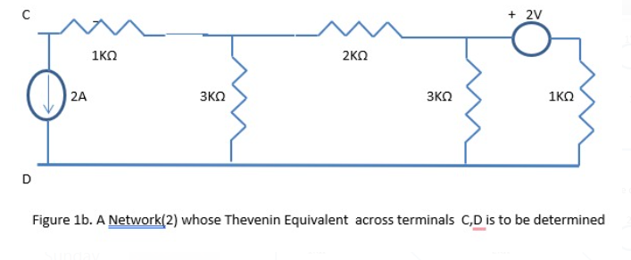
Figure 1a. shows a circuit consisting of impedance elements and AC independent and dependent sources. Figure 1b. describes another pure resistive network consisting of DC sources.

Computation of Equivalent Thevenin voltage and equivalent Thevenin impedance for Figure 1a-1d:
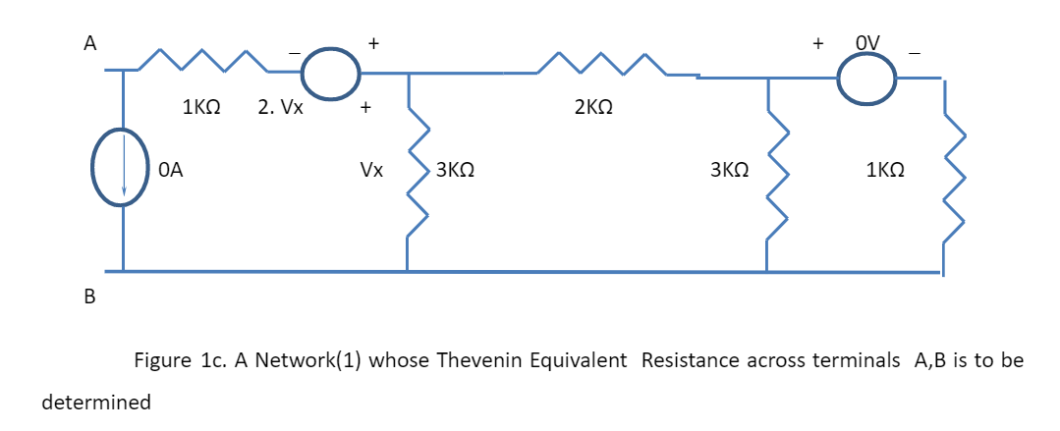
The individual Thevenin open circuit voltages are obtained for Figures 1a&b using Spice/Pspice files TABLE I. They are multiplied and stored in a single voltage source. The individual Thevenin resistances are computed using Figures 1c &d. The two Thevenin resistances are multiplied and stored in a Spice model for resistor. A one ampere DC current source is used at the input of Figures 1c-d to obtain two Thevenin resistances.
TABLE I. SPICE/PSPICE FILE DESCRIPTION TO OBTAIN NEW THEVENIN CIRCUIT
| **** 04/12/23 10:07:00 ****** PSpice Lite (October 2012) ****** ID# 10813 **** |
| NEW THEVENIN CIRCUIT |
| **** CIRCUIT DESCRIPTION |
| ****************************************************************************** |
| *EAMPLE I |
| I10 1 0 DC 1 |
| R12 1 2 1K |
| E32 3 2 3 0 2 |
| R30 3 0 3K |
| R34 3 4 2K |
| R40 4 0 3K |
| V45 4 5 DC 1 |
| R50 5 0 1K |
| *CIRCUIT TO OBTAIN THEVENIN IMPEDANCE (1) |
| I06 0 6 DC 1 |
| R67 6 7 1K |
| E87 8 7 8 0 2 |
| R89 8 9 2K |
| R90 9 0 3K |
| R990 9 0 1K |
| *EXAMPLE II THEVENIN CIRCUIT |
| I100 10 0 DC 2 |
| R1011 10 11 1K |
| R110 11 0 3K |
| R1112 11 12 2K |
| R120 12 0 3K |
| V1213 12 13 DC 2 |
| R130 13 0 1K |
| *CIRCUIT TO OBTAIN THEVENIN IMPEDANCE (2) |
| I014 0 14 DC 1 |
| R1415 14 15 1K |
| R150 15 0 3K |
| R1516 15 16 2K |
| R160 16 0 3K |
| R1660 16 0 1K |
| *EQUIVALENT THEVENIN OPENCIRCUIT VOLTAGE |
| *MULTIPLICATION OF TWO THEVENIN OPEN CIRCUIT VOLTAGES |
| *MULTIPLICATION OF TWO THEVENIN RESISTANCES |
| *LOAD 100 OHMS |
| VTOTAL 17 0 DC -2.11495E06 |
| R1718 17 18 11.854E06 |
| R180 18 0 100 |
| .END |
| **** 04/12/23 10:07:00 ****** PSpice Lite (October 2012) ****** ID# 10813 **** |
| NEW THEVENIN CIRCUIT |
| **** SMALL SIGNAL BIAS SOLUTION TEMPERATURE = 27.000 DEG C |
| ****************************************************************************** |
| NODE VOLTAGE NODE VOLTAGE NODE VOLTAGE NODE VOLTAGE |
| ( 1) 434.3900 ( 2) 1434.4000 ( 3)-1434.4000 ( 4) -390.6500 |
| ( 5) -391.6500 ( 6)-1750.0000 ( 7)-2750.0000 ( 8) 2750.0000 |
| ( 9) 750.0000 ( 10)-4868.8000 ( 11)-2868.8000 ( 12) -781.3000 |
| ( 13) -783.3000 ( 14) 2434.8000 ( 15) 1434.8000 ( 16) 391.3000 |
| ( 17)-2.115E+06 ( 18) -17.8420 |
| VOLTAGE SOURCE CURRENTS |
| NAME CURRENT |
| V45 -3.917E-01 |
| V1213 -7.833E-01 |
| VTOTAL 1.784E-01 |
| TOTAL POWER DISSIPATION 3.77E+05 WATTS |
| JOB CONCLUDED |
V(18) in TABLE I is the output voltage for new Thevenin equivalent circuit with 100 Ohm load.
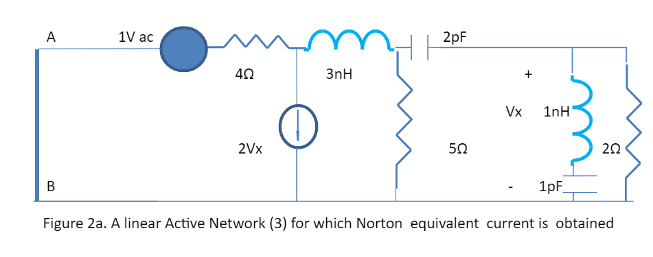
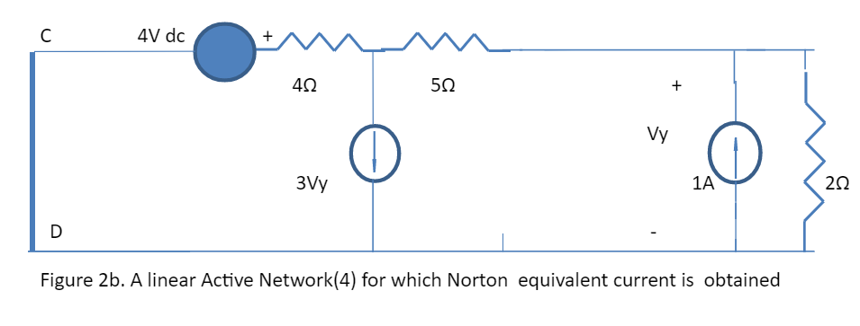
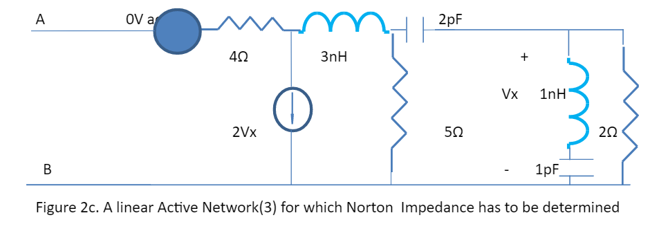
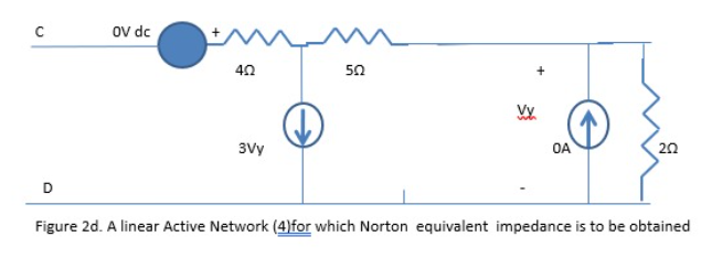
Computation of Equivalent Norton Current and equivalent Norton impedance for Figure 2a-d :
The individual short circuit currents and Norton impedances are obtained for Figures 2a-b, and Figure 2c-d, using Spice/Pspice files (TABLE II) . They are added and stored using Pspice [5-10] with circuit commands. The division of individual Norton impedances are obtained through the following technique which can be easily implemented by SPICE or PSpice circuit file. Figure 3 describes the technique using an operational amplifier, used as inverted amplifier with 1 ohm feedback, and Norton impedance Zn2 as input impedance and input voltage as Norton impedance Zn1.
The output would yield the division of Rn1 and Rn2. Again, the values of divisions which are equivalent to new Norton impedance in ingeneously stored using Pspice FREQ option.
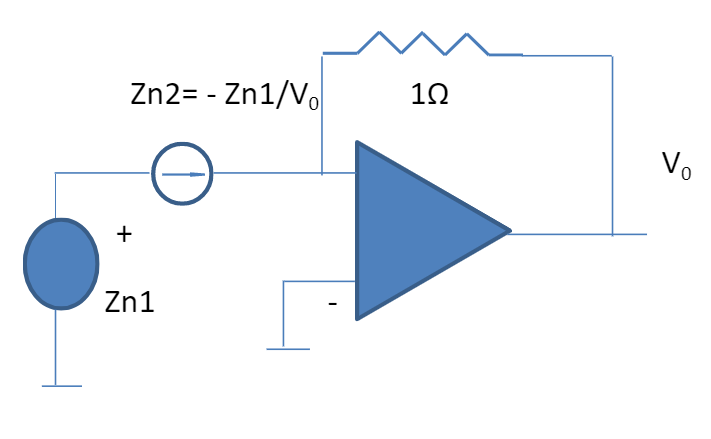
Figure 3. A Opamp technique to obtain division of two impedances
The circuit in Figure 3 is implemented to obtain ratio of Norton Impedances. The two Norton short circuit currents are added and the ratio of impedances are stored by using Analog behavioural FREQ option of PSpice, to obtain new Norton equivalent.
TABLE II SPICE/PSPICE CIRCUIT FILE TO OBTAIN NEW NORTON CIRCUIT
| **** 04/12/23 10:21:57 ****** PSpice Lite (October 2012) ****** ID# 10813 **** |
| EXAMPLE NEW NORTON CIRCUIT |
| **** CIRCUIT DESCRIPTION |
| ****************************************************************************** |
| V10 1 0 AC 1 |
| R12 1 2 4 |
| G20 2 0 4 0 2 |
| L23 2 3 3NH |
| R30 3 0 5 |
| C34 3 4 2PF |
| L45 4 5 1NH |
| C50 5 0 1PF |
| R40 4 0 2 |
| *CIRCUIT TO OBTAIN NORTON IMPEDANCE (1) |
| I06 0 6 AC 1 |
| R67 6 7 4 |
| G70 7 0 9 0 2 |
| L78 7 8 3NH |
| R80 8 0 5 |
| C89 8 9 2PF |
| L910 9 10 1NH |
| C100 10 0 1PF |
| R90 9 0 2 |
| *EXAMPLE II NORTON CIRCUIT |
| V110 11 0 AC 4 |
| R1112 11 12 4 |
| G120 12 0 13 0 3 |
| R1213 12 13 5 |
| I013 0 13 AC 1 |
| R300 13 0 2 |
| *CIRCUIT TO OBTAIN NORTON IMPEDANCE (2) |
| V1518 15 25 |
| R1516 25 16 4 |
| G160 16 0 17 0 3 |
| R1617 16 17 5 |
| R170 17 0 2 |
| *DIVISION OF TWO NORTON IMPEDANCES |
| EN 15 0 18 19 1 |
| FGT 18 19 V1518 1 |
| E1819 18 0 6 0 1 |
| R2021 19 20 1 |
| E210 20 0 19 0 1E15 |
| R190 19 0 1E12 |
| *CALCULATION OF NORTON IMPEDANCE 2 |
| RR1516 22 23 4 |
| GG160 23 0 24 0 3 |
| RR1617 23 24 5 |
| RR170 24 0 2 |
| I022 0 22 AC 1 |
| E260 26 0 FREQ {I(V2526)}=(1GHZ,12.21958,51.43) (2GHZ,16.491,52.86) (5GHZ,23.568,85.22) (10GHZ,23.2811,52.6) |
| F025 0 27 V10 1 |
| F1025 0 27 V110 1 |
| R2527 27 28 0.00001 |
| V2526 28 26 |
| R250 27 0 700 |
| .AC LIN 10 1GHZ 10GHZ |
| .PRINT AC VM(0,20) VP(0,20) |
| .PRINT AC IM(V10) IP(V10) IM(V110) IP(V110) |
| .PRINT AC IR(V10) II(V10) IR(V110) II(V110) |
| .PRINT AC IR(R250) II(R250) |
| .PRINT AC IR(V2526) II(V2526) |
| .PRINT AC VM(27) VP(27) |
| .PRINT AC VM(22) VP(22) VM(18) VP(18) |
| .END |
| **** 04/12/23 10:21:57 ****** PSpice Lite (October 2012) ****** ID# 10813 **** |
| EXAMPLE NEW NORTON CIRCUIT |
| **** SMALL SIGNAL BIAS SOLUTION TEMPERATURE = 27.000 DEG C |
| ********************************************************** |
| NODE VOLTAGE NODE VOLTAGE NODE VOLTAGE NODE VOLTAGE |
| ( 1) 0.0000 ( 2) 0.0000 ( 3) 0.0000 ( 4) 0.0000 |
| ( 5) 0.0000 ( 6) 0.0000 ( 7) 0.0000 ( 8) 0.0000 |
| ( 9) 0.0000 ( 10) 0.0000 ( 11) 0.0000 ( 12) 0.0000 |
| ( 13) 0.0000 ( 15) 0.0000 ( 16) 0.0000 ( 17) 0.0000 |
| ( 18) 0.0000 ( 19) 0.0000 ( 20) 0.0000 ( 22) 0.0000 |
| ( 23) 0.0000 ( 24) 0.0000 ( 25) 0.0000 ( 26) 0.0000 |
| ( 27) 0.0000 ( 28) 0.0000 |
| VOLTAGE SOURCE CURRENTS |
| NAME CURRENT |
| V10 0.000E+00 |
| V110 0.000E+00 |
| V1518 0.000E+00 |
| V2526 0.000E+00 |
| TOTAL POWER DISSIPATION 0.00E+00 WATTS |
| **** 04/12/23 10:21:57 ****** PSpice Lite (October 2012) ****** ID# 10813 **** |
| EXAMPLE NEW NORTON CIRCUIT |
| **** AC ANALYSIS TEMPERATURE = 27.000 DEG C |
| FREQ VM(0,20) VP(0,20) |
| 1.000E+09 4.083E+00 5.143E+01 |
| 2.000E+09 6.677E+00 5.286E+01 |
| 3.000E+09 8.429E+00 5.124E+01 |
| 4.000E+09 9.526E+00 5.215E+01 |
| 5.000E+09 1.508E+01 8.522E+01 |
| 6.000E+09 1.228E+01 4.316E+01 |
| 7.000E+09 1.265E+01 4.664E+01 |
| 8.000E+09 1.325E+01 4.883E+01 |
| 9.000E+09 1.391E+01 5.077E+01 |
| 1.000E+10 1.459E+01 5.260E+01 |
| **** 04/12/23 10:21:57 ****** PSpice Lite (October 2012) ****** ID# 10813 **** |
| EXAMPLE NEW NORTON CIRCUIT |
| **** AC ANALYSIS TEMPERATURE = 27.000 DEG C |
| ****************************************************************************** |
| FREQ IM(V10) IP(V10) IM(V110) IP(V110) |
| 1.000E+09 4.898E-02 1.286E+02 1.600E+00 1.800E+02 |
| 2.000E+09 2.995E-02 1.271E+02 1.600E+00 1.800E+02 |
| 3.000E+09 2.373E-02 1.288E+02 1.600E+00 1.800E+02 |
| 4.000E+09 2.099E-02 1.278E+02 1.600E+00 1.800E+02 |
| 5.000E+09 1.327E-02 9.478E+01 1.600E+00 1.800E+02 |
| 6.000E+09 1.628E-02 1.368E+02 1.600E+00 1.800E+02 |
| 7.000E+09 1.581E-02 1.334E+02 1.600E+00 1.800E+02 |
| 8.000E+09 1.509E-02 1.312E+02 1.600E+00 1.800E+02 |
| 9.000E+09 1.438E-02 1.292E+02 1.600E+00 1.800E+02 |
| 1.000E+10 1.371E-02 1.274E+02 1.600E+00 1.800E+02 |
| **** 04/12/23 10:21:57 ****** PSpice Lite (October 2012) ****** ID# 10813 **** |
| EXAMPLE NEW NORTON CIRCUIT |
| **** AC ANALYSIS TEMPERATURE = 27.000 DEG C |
| ****************************************************************************** |
| FREQ IR(V10) II(V10) IR(V110) II(V110) |
| 1.000E+09 -3.054E-02 3.830E-02 -1.600E+00 0.000E+00 |
| 2.000E+09 -1.809E-02 2.388E-02 -1.600E+00 0.000E+00 |
| 3.000E+09 -1.486E-02 1.850E-02 -1.600E+00 0.000E+00 |
| 4.000E+09 -1.288E-02 1.658E-02 -1.600E+00 0.000E+00 |
| 5.000E+09 -1.106E-03 1.322E-02 -1.600E+00 0.000E+00 |
| 6.000E+09 -1.188E-02 1.114E-02 -1.600E+00 0.000E+00 |
| 7.000E+09 -1.086E-02 1.149E-02 -1.600E+00 0.000E+00 |
| 8.000E+09 -9.934E-03 1.136E-02 -1.600E+00 0.000E+00 |
| 9.000E+09 -9.094E-03 1.114E-02 -1.600E+00 0.000E+00 |
| 1.000E+10 -8.326E-03 1.089E-02 -1.600E+00 0.000E+00 |
| **** 04/12/23 10:21:57 ****** PSpice Lite (October 2012) ****** ID# 10813 **** |
| EXAMPLE NEW NORTON CIRCUIT |
| **** AC ANALYSIS TEMPERATURE = 27.000 DEG C |
| ****************************************************************************** |
| FREQ IR(R250) II(R250) |
| 1.000E+09 -6.115E-03 -7.242E-03 |
| 2.000E+09 -9.536E-03 -1.202E-02 |
| 3.000E+09 -1.021E-02 -1.944E-02 |
| 4.000E+09 -8.350E-03 -2.710E-02 |
| 5.000E+09 -3.885E-03 -3.420E-02 |
| 6.000E+09 -7.649E-03 -3.341E-02 |
| 7.000E+09 -1.126E-02 -3.200E-02 |
| 8.000E+09 -1.466E-02 -3.025E-02 |
| 9.000E+09 -1.781E-02 -2.819E-02 |
| 1.000E+10 -2.071E-02 -2.582E-02 |
| **** 04/12/23 10:21:57 ****** PSpice Lite (October 2012) ****** ID# 10813 **** |
| EXAMPLE NEW NORTON CIRCUIT |
| **** AC ANALYSIS TEMPERATURE = 27.000 DEG C |
| ****************************************************************************** |
| FREQ IR(V2526) II(V2526) |
| 1.000E+09 -1.624E+00 4.554E-02 |
| 2.000E+09 -1.609E+00 3.590E-02 |
| 3.000E+09 -1.605E+00 3.794E-02 |
| 4.000E+09 -1.605E+00 4.368E-02 |
| 5.000E+09 -1.597E+00 4.742E-02 |
| 6.000E+09 -1.604E+00 4.455E-02 |
| 7.000E+09 -1.600E+00 4.350E-02 |
| 8.000E+09 -1.595E+00 4.161E-02 |
| 9.000E+09 -1.591E+00 3.933E-02 |
| 1.000E+10 -1.588E+00 3.671E-02 |
| **** 04/12/23 10:21:57 ****** PSpice Lite (October 2012) ****** ID# 10813 **** |
| EXAMPLE NEW NORTON CIRCUIT |
| **** AC ANALYSIS TEMPERATURE = 27.000 DEG C |
| ****************************************************************************** |
| FREQ VM(27) VP(27) |
| 1.000E+09 6.635E+00 -1.302E+02 |
| 2.000E+09 1.074E+01 -1.284E+02 |
| 3.000E+09 1.537E+01 -1.177E+02 |
| 4.000E+09 1.985E+01 -1.071E+02 |
| 5.000E+09 2.410E+01 -9.648E+01 |
| 6.000E+09 2.399E+01 -1.029E+02 |
| 7.000E+09 2.375E+01 -1.094E+02 |
| 8.000E+09 2.353E+01 -1.158E+02 |
| 9.000E+09 2.334E+01 -1.223E+02 |
| 1.000E+10 2.317E+01 -1.287E+02 |
| **** 04/12/23 10:21:57 ****** PSpice Lite (October 2012) ****** ID# 10813 **** |
| EXAMPLE NEW NORTON CIRCUIT |
| **** AC ANALYSIS TEMPERATURE = 27.000 DEG C |
| ****************************************************************************** |
| FREQ VM(22) VP(22) VM(18) VP(18) |
| 1.000E+09 5.000E+00 0.000E+00 2.042E+01 5.143E+01 |
| 2.000E+09 5.000E+00 0.000E+00 3.338E+01 5.286E+01 |
| 3.000E+09 5.000E+00 0.000E+00 4.214E+01 5.124E+01 |
| 4.000E+09 5.000E+00 0.000E+00 4.763E+01 5.215E+01 |
| 5.000E+09 5.000E+00 0.000E+00 7.538E+01 8.522E+01 |
| 6.000E+09 5.000E+00 0.000E+00 6.141E+01 4.316E+01 |
| 7.000E+09 5.000E+00 0.000E+00 6.325E+01 4.664E+01 |
| 8.000E+09 5.000E+00 0.000E+00 6.626E+01 4.883E+01 |
| 9.000E+09 5.000E+00 0.000E+00 6.954E+01 5.077E+01 |
| 1.000E+10 5.000E+00 0.000E+00 7.296E+01 5.260E+01 |
The equivalent Norton circuit parameters of new circuit can be verified by the results presented in TABLE II.
III CONCLUSION
SPICE/PSPICE Circuit simulation and analysis program has been used to obtain equivalents for a new circuit whose Thevenin parameters are
multiples of individual Thevenin parameters of two given circuits and have been verified. Similarly, SPICE/PSPICE Circuit program is used to obtain equivalents for a new Norton circuit whose Norton parameters are sum of individual Norton short circuit currents and numerical complex division of individual Norton impedances.


