

Flight electronics rarely fail from a single dramatic event. More often, sustained vibration accumulates fatigue in solder joints, connectors and attachment points until a marginal design becomes a field failure.
For engineers and product developers, the core questions are which vibration paths matter most and how isolation should be matched to them. This guide draws on insights from Isolation Dynamics Corp. (IDC), a U.S.-based manufacturer of aerospace vibration isolation products, to explain how engineers can match isolator type, material behavior and qualification requirements to the vibration path.
How Vibration Reaches Sensitive Electronics
Vibration enters avionics through structure-borne paths, such as engine and gearbox mounting points, rotor harmonics, airframe response to aerodynamic loading and, for spaceflight hardware, launch random vibration. A 2023 study identifies random vibration between 20 and 2000 Hz as one of the main causes of mechanical failure in spaceborne electronic units, largely because repeated bending of circuit boards fatigues solder joints.
IDC, a manufacturer of shock and vibration isolation products, supports aerospace use cases with application-specific engineering guidance, U.S.-based manufacturing using domestic materials, and involvement from design through testing and production. IDC says that in fixed-wing aircraft, vibration “can shorten the service life of instrumentation and expensive avionics devices.” The same environment can also threaten engine-adjacent hardware such as exhaust systems and supply lines.
Reliability research points the same way. Airborne component testing found that combined thermal cycling and random vibration produced a much shorter fatigue life than either load alone, with failures concentrated at component corners. Vibration and thermal exposure should therefore be evaluated together rather than in isolation.
Matching Isolator Types to the Vibration Path
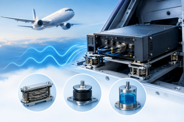
No isolator family suits every path, so the useful question is what a given path demands. Three families cover most avionics installations.
Wire Rope Isolators
Wire rope isolators suit paths that combine shock with broadband vibration. Stranded steel cable between retaining bars dissipates energy through friction between strands. These isolators react to loads in any direction with stiffness tunable by design. Their behavior is nonlinear, however. Small-amplitude testing found that vibration amplitude shaped stiffness and damping more clearly than preload or frequency, so engineers should characterize them at expected input levels rather than rely on a single spring rate.
Elastomeric Isolators
Elastomeric isolators suit compact installations such as avionics racks, where compound and geometry can be tuned to the load. IDC notes that engineered rubber compounds can “reduce structure-borne noise, offer energy absorption and mitigate shocks.” The limitation is environmental sensitivity. A 2024 study of isolators for small unmanned aircraft payloads finds that rubber properties depend heavily on temperature, so the operating range should be defined before a compound is chosen.
Liquid-Damped Mounts
Liquid-damped mounts suit high-amplitude environments where resonance control matters most. A viscous fluid or silicone gel forms part of the damper and converts kinetic energy to heat. As a starting point, shock-dominated or high-amplitude inputs favor wire rope or liquid-damped designs, while compact racks with moderate inputs and controlled temperatures favor elastomeric mounts.
Durable Materials for Aerospace Vibration Dampers
No single material suits every platform, so durability should be judged at the system level. Steel wire rope tolerates wide temperature swings and shock, while engineered elastomers offer tear resistance and elasticity, though they generally stiffen in the cold and soften with heat. Silicone gel dampers dissipate energy across a wide temperature range, and stainless steel housings protect sealed assemblies from corrosion.
Dynamic fatigue life ties these choices together. Higher resonance amplification accelerates fatigue damage, shortening the mean time to failure of the isolator and the protected electronics. On rotary-wing platforms, sustained vibration makes long-term wear a central criterion.
Verifying Performance Against Qualification Standards
For civil avionics, RTCA DO-160 defines standard, robust and high-level short-duration vibration tests, with test curves chosen by aircraft type and installation zone. For spaceflight payloads, NASA-STD-7001 addresses acoustic and random vibration environments and test levels.
These programs commonly apply loads axis by axis, but service environments can excite all six degrees of freedom, including translation along the X, Y and Z axes and rotation in pitch, roll and yaw. True multi-axis testing applies dynamic loads across multiple orthogonal axes simultaneously, and sequential single-axis tests are not multi-axis. Qualification should also reflect the mounted configuration, since isolators change dynamic response.
Frequently Asked Questions
These answers address the main considerations for matching aerospace vibration isolation solutions to avionics hardware, operating conditions and qualification requirements.
How do I choose the right vibration mount for an avionics system?
Start with the disturbing frequencies, supported mass, center of mass and temperature range. Set a target natural frequency well separated from dominant excitation, balance damping against high-frequency isolation, and confirm the choice with transmissibility and stiffness data.
What are the most durable materials for aerospace vibration dampers?
No single material leads in every case. Steel wire rope, engineered elastomers, silicone gel dampers and stainless steel housings each serve different environments. Compare dynamic fatigue life, temperature response and MTTF against the actual mission profile.
What are the top-rated vibration isolation solutions for aerospace?
The right solution depends on the vibration environment, the equipment and the installation. Three passive families cover most avionics installations — wire rope isolators for combined shock and broadband vibration, elastomeric mounts for compact installations, and liquid-damped mounts for high-amplitude environments. Active isolation can serve precision payloads, but it adds cost and complexity.
Confirm any choice against transmissibility data and the applicable qualification standard, such as RTCA DO-160.
What is the difference between isolation and damping?
Isolation limits the vibration transmitted into a system. Damping dissipates vibration energy as heat. Isolators often contain damping elements.
Which standards apply to avionics vibration testing?
RTCA DO-160 Section 8 covers civil airborne equipment, and NASA-STD-7001 covers spaceflight payloads. Military programs may also invoke MIL-STD-810, the Department of Defense standard that covers testing methods to see how equipment performs under real-world physical and climatic stresses.
Matching Isolation to the Environment
Protecting flight electronics from sustained vibration starts with understanding how it reaches the hardware. IDC’s aerospace guidance frames isolation as an application-specific engineering problem, where the vibration path, supported mass, temperature range and qualification standard all shape the final mount selection. Structure-borne paths and combined thermal and vibration loading shorten fatigue life when left unmanaged.
Matching wire rope, elastomeric or liquid-damped isolation to the path, setting a natural frequency away from dominant excitation, and balancing damping against high-frequency attenuation all help reduce that risk. Qualification testing against relevant standards then confirms performance, ideally with attention to all six degrees of freedom.