


The STPD01 is ST’s first programmable DC-DC Buck Converter for USB-C Power Delivery applications up to 60 W and the first in the industry to provide cable drop compensation. Engineers simply need to use the I<sup>2</sup>C interface to configure it from 3 V to 20 V using small increments. It gives teams flexibility and precision, leading to more compact and cost-effective designs. Additionally, the device includes a broad range of input voltages and protection features. Hence, designers can simplify and optimize internal operations and layouts to scale designs more efficiently and reduce their time to market.
The rise of USB-C PD and its inherent challenges
How are USB Power Delivery and USB-C transformative technologies?
It’s hard to understate the transformative aspect of USB Power Delivery. Fast charging is now everywhere, and the ability to deliver up to vastly more output voltages means powering products with a USB port instead of an expensive and cumbersome connector, for instance. Moreover, as USB Power Delivery is coming up alongside USB-C, it’s no wonder that the European Union is mandating the new connector on consumer devices to promote interoperability and reduce electronic waste. USB-C PD is changing consumer and industrial electronics, from cars to displays, wall chargers, phones, remotes, laptops, TVs, and more, and it’s only the beginning. According to Future Market Insights, the USB Type-C market should reach 127 billion dollars by 2030.
Why USB Power Delivery forces engineers to adopt new designs?
The challenge is that engineers must rethink their power stage. While previous USB standards stopped at 5 V, USB PD 3.0 shoots up to 20 V, and the 3.1 version climbs up to 48 V. Hence, designers must deal with far greater loads and new communication exchanges between the source and sink devices. Moreover, as USB-C PD penetrates more markets, companies must find ways to scale their designs to optimize operations. However, a power stage for a computer display will have significant differences compared to a wall charger. Additionally, companies must offer greater protection against hazardous conditions, especially since consumers are not always using high-quality cables or devices.
STPD01 provides flexibility
The solution for the scalability challenge
Companies are looking to scale their power stage to reuse as much of their design as possible. Consequently, the STPD01 has a wide input range from 6 V to 26.4 V to support many different applications. Teams can thus qualify the ST device once and utilize it in multiple systems to get greater returns. Teams get familiar with the product, and larger volumes open the door to lower unit prices. Concretely, it means designers could work on power stages for a smartphone, a wall charger with multiple ports, and one for a display and reuse the STPD01. Additionally, its straightforward programmability means that teams could recycle some of their application code and tailor the values for their product.
While the input voltage range is wide, the STPD01 doesn’t support applications above 3 A, which is why it maxes out at 60 W, as USB PD 3.0 doesn’t deliver more than 20 V. The reason for this technical specification is that all USB-C cables support a maximum of 3 A. Beyond that, the cable must include an IC that will communicate with the source and have wires capable of delivering 5 A. Since most consumer applications need fewer than 60 W, the STPD01 decided to target solutions that didn’t require dedicated cables, to offer a better price-per-performance ratio.
The solution to the optimization challenge
The ability to program the STPD01 by using the I<sup>2</sup>C interface also comes with the ability to use small increments. The current can be set from 0.1 A to 3 A with 100 mA steps. Similarly, from 3 V to 5.9 V, the ST device supports 20 mV steps, and between 5.9 V and 11 V, engineers have access to 100 mV increments, while output voltages between 11 V and 20 V can be set using 200 mV steps. Consequently, engineers have far greater precision, which enables them to create more compact systems. Teams can create specific profiles and reduce the size of some of the passive components.
STPD01 provides robustness
The solution to voltage drops due to copper tracks
As applications handle greater power, providing a robust solution is critical. It’s why the STPD01 is unique in offering cable drop compensation. Put simply, the STPD01 is smart enough to increase its output voltage above the defined value to compensate for drops due to copper tracks or output cable resistance. As the load increases, the device modifies the current flowing in the high side of the voltage-feedback resistor divider to regulate the load voltage. The feature is not new, but engineers had to implement it externally. Thanks to cable compensation in the STPF01, engineers no longer need to add sensors monitoring the voltage out from the regulator to the load.
The solutions to provide better protection
The STPD01 also includes overvoltage, overcurrent, and overtemperature protections. In most cases, detecting an overvoltage event puts the half-bridge in high impedance until the critical condition passes. Additionally, in some cases, the system resets the output voltage to 5 V. Similarly, overcurrent protection drops the voltage out if triggered. Finally, the overtemperature and short-circuit protection switches the high-side and low-side devices off while resetting certain parameters.
Another feature present in the STDP01 is clock dithering. In a nutshell, the mechanism dithers the oscillator’s frequency to spread the noise, reduce peaks, and thus limit electromagnetic interferences. The ST device dithers by about 5%, limiting EMI emissions without resorting to large inductors or massively increasing switching losses. Moreover, when using many STPD01 in a multi-port system, the clock dithering feature helps spread switching currents to avoid piling up interferences. Indeed, as the ST reference design shows, the STPD01 is a prime candidate for multi-port systems.
Where to Get Started?
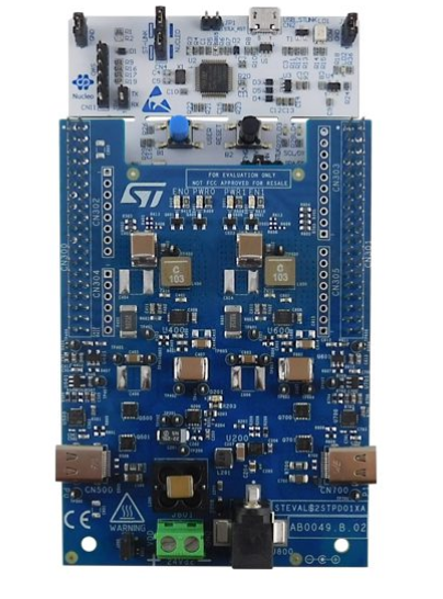
The best way to experiment with the STPD01 is to grab the STEVAL-2STPD01 evaluation kit. The board provides two USB-C ports, each capable of delivering 60 W, for a total of 120 W. The board uses a NUCLEO-G071RB for its host MCU. Additionally, two TCPP02-M18 provide special VBUS, CC, and VCONN protections. The evaluation kit thus highlights the ability to leverage the ST ecosystem to create the entire USB-C PD multi-port application. We even ship a software package for the STPD01 evaluation kit, the STSW-2STPD01, which comes with profiles and power-sharing modules. Engineers can thus take ST’s implementation and more rapidly code their firmware.
For more information visit ST Blog Here.


