


Antenna for Non-GEO Space Applications
Abstract
The adoption of active electronically scanned antennas (AESAs) for satellite communication (satcom) has offered greater flexibility for operators and consumers. This article will review the design considerations when choosing antenna front-end (FE) components (low noise amplifiers and power amplifiers) for use in these beamforming arrays.
Introduction
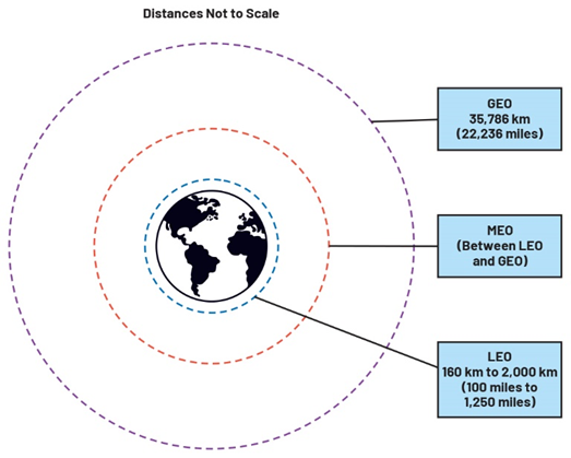
We have lived with satellite technology for over 60 years. Even though the early satellites were launched to low Earth orbit (LEO)i due to launch and size limitations, we are most familiar with satellites in geosynchronous Earth orbit (GEO)ii where they have provided multiple key services such as telecom, satellite TV, Earth observation, and of course a range of services for governments and their military. However, a major shift has occurred to now position LEO and medium Earth orbit (MEO)iii as the most attractive orbits for a range of large constellations offering a range of data-based services (satcom, Earth observation and mapping, navigation and positioning etc.). Figure 1 shows the relative positioning of LEO, MEO, and GEO orbits.
This move to non-GEO has come about due to the confluence of lower launch costs, adoption of mass manufacturing techniques for satellites, technical advancements in communications and antenna technology and sensors, optical technology for inter-satellite links, and the availability of large amounts of private capital to fund these large programs.
The increasing use of spacecraft in LEO poses new challenges for designers of on-orbit satcom links. The fixed communication links of GEO have been replaced with links that need to be adaptable to allow them to communicate with locations on Earth even as they orbit Earth at speeds in the range of 7.5 km/s. AESAs are being used in these modern satcom systems to not only provide the ability to adaptively steer the antenna’s signal in the correct direction of its intended target but also to support multiple beams, which allows multiple users to be supported simultaneously. On-orbit satellites have unique requirements for component selection, and this is particularly the case for the FE components that interface the antenna elements to the transmit and receive signal chains. This article will explore the design considerations for FE (amplifier) component selection in such systems.
The Move from GEO to LEO
GEO Satellites Provided a Good Service—So Why Change?
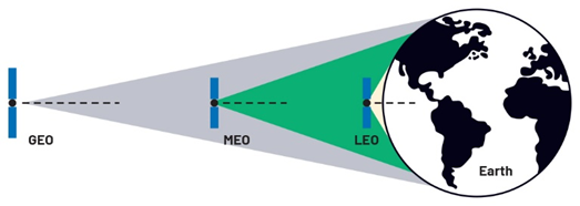
Despite the drawbacks of high launch costs, satellites in GEO had a significant advantage, namely that that they were at a fixed position in the sky due to the orbit being synchronous with the Earth’s rotation. This allowed the deployment of fixed-position satellite antennas and relatively low cost VSAT terminals with parabolic dish antennas—key enablers of data services and most notably direct-to-home (DTH) satellite TV services. Satellites in GEO have the largest Earth-coverage (as shown in Figure 2) with only three GEO satellites required to provide global coverage.iv
Despite the stated advantages of GEO, the move toward satellites in LEO has several key drivers mostly concentrated on evolving communication networks. We live in a highly connected world, but the reality is that a significant proportion of the world’s population live in areas that are either not served or are underserved by internet connectivity—for example, GEO that is positioned on an equatorial plane has reduced service in polar regions. Large satcom constellations in LEO can bring relatively high speed connectivity to these areas. For areas that are currently served by internet connectivity, LEO constellations promise even higher data rates—equivalent to fiber—for both consumers and B2B. The size of the proposed LEO constellations including some in-built redundancy brings the advantage of network resiliency due to the larger number of available satellites. This resiliency is of interest to government and military users as well as the commercial world. Finally, the lower manufacturing and launch costs mean that a satellite network can easily be upgraded as the new technology becomes available.
i LEO is defined as being between ~160 km and 2000 km above the Earth’s surface.
ii GEO is defined as being 35,786 km (22,236 miles) above Earth’s surface.
iii MEO is between LEO and GEO—for example, O3b is in MEO at 8000 km above Earth’s surface.
iv Coverage is limited in northern and southern latitudes.
Satellite Orbits
A non-GEO constellation is configured using satellites in specific orbits or in a mixture of orbits. The more popular orbits include the equatorial orbit (used by the SES O3b mPOWER constellation in MEO) where the satellites generally follow the equator, the inclined orbit that is tilted from an equatorial orbit by a number of degrees and track from west to east in the same direction as Earth’s rotation, and the polar orbit where each satellite will follow a particular line of longitude while orbiting over each pole (for example, OneWeb). Several of the large LEO constellations, such as Telesat Lightspeed and SpaceX Starlink, will use a hybrid of inclined and polar orbits to provide optimal coverage in the northern regions as inclined orbits can only operate to a certain latitude. Polar orbits provide the best global coverage of the three orbit categories, but due to additional fuel use for positioning they are primarily used to provide additional coverage of northern latitudes combined with shells of satellites in inclined orbits. Polar orbits are also more exposed to radiation effects. Satellites are arranged in circular planes, each with constant height above Earth. The size of the constellation is given by the number of planes multiplied by the number of satellites per plane (see Figure 3).v
Enter the LEO Constellation
Some constellations have launched, or there are plans to launch, hundreds, in certain cases thousands, of small satellites into LEO. Satellites in LEO offer two distinct advantages for satcom over GEO links. Firstly, signal latency is reduced due to the height of the orbit. The signal path from Earth to a LEO satellite is much shorter (~1/35 of that of a GEO satellite), reducing signal latency by an order of magnitude to ~25 ms, which some believe will enable LEO satcom to partake in the expansion of 5G services with its promise of data intensive real-time services. The second advantage is that an individual LEO satellite’s data capacity is concentrated on a much smaller area, potentially giving individual users a much larger data bandwidth—subject to the overall data capacity of the constellation. Within the coverage area, the satellite would typically generate multiple downlink beams to link to many users/hubs. These spatially separated beams allow reuse of allocated frequencies, which can avoid interbeam interference and optimize data availability. High throughput satellites (HTS and vHTS) can also provide this data concentration; however, the overall data capacity of a GEO satellite is lower than that of a typical LEO constellation.vi A limitation of large constellations with high data capacity is that only a fraction (33% to 50%) of that overall data capacity is available to users at one time since many of the constellation spacecraft will be flying over oceans or uninhabited areas of Earth.
v There may also be some additional satellites used as backup for redundancy.
vi Telesat Lightspeed was originally designed for 15 Tbps data capacity from 294 satellites. A typical VHTS would offer 2 Tbps to 3 Tbps data capacity (2022).
Constellation Size Impact on Cost and Mission Life
Constellation satellites are cheaper to build thanks to the use of mass production techniques and because lower cost, nonhermetic, often plastic encapsulated, components can be used due to the shorter mission life and less harsh radiation environment. The mission lifetime of LEO satellites is typically 5 years to 7 years due to increased fuel usage for maintaining orbit as there is increased atmospheric drag in LEO and LEO satellites have limited fuel capacity due to their smaller size. Radiation tolerance requirements are typically lower for LEO satellites. For example, the acceptable level for total ionizing dose (TID)vii performance of a component to be used in a LEO satellite could be in the region of 30 krad, whereas 100 krad is typically required for a GEO mission due to its longer mission life and higher radiation exposure.

Challenges of LEO and Key-Enabling Technologies
There is an increased complexity in managing the flow of data to the constellation. Data is routed from the Earth station(s) through the constellation via intersatellite links (ISL) using either radio or optical links. This is necessary as LEO satellites may not always be in sight of an Earth station.
Non-GEO satellites move across the sky when viewed from Earth as opposed to the fixed position of GEO satellites. This is a factor of the orbital speed required to maintain their orbit. Due to increased atmospheric drag and a lower orbit, LEO satellites must be faster than satellites at higher orbits. One of the satellite shells proposed for the Starlink constellation is positioned at 550 km above Earth. At that altitude, flight velocity is 7.5 km/s, which means that an individual satellite in this shell will only be visible to a user for 4.1 minutes. A user of a GEO satellite can use a fixed antenna positioned on the satellite, whereas a user of a LEO satellite service must use an antenna that can track the LEO satellite as it crosses the sky. Similarly, the satellite’s antenna must be able to track the served area on Earth as it moves in its orbit. Satellites in MEO such as the O3b constellation have used mechanically steered antennas, possible due to their slower orbital speed. LEO satellites must use some form of AESA as mechanical steering systems could not meet the tracking requirements. Concurrent with the need for steerable beams in LEO is the general requirement for multiple beams. Multiple beams allow satellites to optimize service and data throughput to multiple data gateways or served areas. What is needed for LEO applications is an antenna that can support electronic beam steering of multiple beams independently. Some constellations propose up to 16 steerable user beams per satellite.
The key to the flexibility of these constellations is the adoption of antennas that support beam steering to maintain the communication links—either primary satcom/EO uplinks/downlinks or the secondary tracking, telemetry, and control (TT&C) links.
AESA and Beamforming
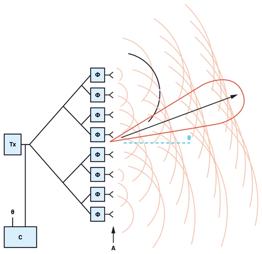
A conventional parabolic antenna typically has a single feed for the transmitter and the receiver and will either be pointed at a fixed position or mechanically steered. An electronic beam steering array antenna is made up of multiple antenna elements whose radiation patterns are designed to constructively combine with those of neighboring elements in the array to form what is called the main lobe—see Figure 4. The main lobe transmits the radiated energy in the desired direction. Ideally, the main lobe would carry all the transmitted energy but due to nonidealities there will be some energy directed in side lobes, which are not in the desired direction. The antenna design seeks to maximize the energy in the main lobe while minimizing that of the side lobes. The main lobe can be shaped and steered by adjusting the individual amplitudes and phases of the antenna elements. Modern IC technology can implement adjustable gain and phase that can be updated in the order of microseconds to provide fast steering even on large arrays of elements for satellite and airborne applications.viii Side-lobe reduction is critical for LEO applications as the side lobes can cause interference due to the proximity of the satellite to Earth.
vii TID—cumulative exposure to ionizing sources can cause shifts in device thresholds, increased leakage, or nonfunctionality.
viii Refer to the following articles for more details on beamforming.
FE Component Selection for AESA
Satcom systems are frequency division duplex (FDD) systems where the transmitter and receiver operate at different frequencies. These systems most often have separate antennas for uplinks and downlinks using the allocated frequency bands.
In common with most applications in the aerospace and defense domain, the size, weight, power, and cost (SWaP-C) are important characteristics that determine the choice of components in systems and subsystems. For on-orbit applications, size and weight are limited by the launch capability with larger and heavier systems being much more expensive to launch. Indeed, in the case of large constellations, each satellite must fit within a predetermined form factor, which allows multiple satellites to be launched from the launch bay of a rocket. Also, as on-orbit systems rely almost entirely on solar energy and battery back-up systems, power consumption is a critical specification when choosing components.
For designers of array antennas for on-orbit applications, the array size and element spacing require that FE components (LNAs for receive antennas; drivers/PAs for transmit antennas) be as small as possible since each element of the array will have its own front end often requiring multiple components, which must be placed as near the element antenna as possible in order to reduce trace losses, which can add directly to noise figure. A typical implementation would feature a beamforming core chip dedicated to several antenna elements with each element then having its own FE devices (LNAs for the receiver and driver and/or PA for the transceiver). High gain receive antennas may implement FEs by placing several high gain LNAs in series to achieve the required input gain. Component size is important in this context as interelement spacing will reduce with higher frequency. In the case of the Ka band receiver (26 GHz to 28 GHz), the element the element spacing is ~5 mm for λ/2 lattice pitch. Maintaining the wide scan angles for LEO applications determines that the array elements must be placed at the λ/2 pitch. For antenna arrays used on GEO platforms, the scan requirements are not as critical (±9), allowing more flexibility in element minimum spacing. The latest LNA form factors in 2 mm × 2 mm packages make it easier to manage critical component placement and many also include DC blocks and RF chokes within the package to further simplify the layout task.
Device performance is critical when selecting amplifiers for on-orbit applications. For LEO satellite receiver antennas, noise figure (NF in dB) is most important as it contributes to the system noise figure, which directly affects the number of elements required in the array and hence the antenna size. Recall that LEO satellites are smaller than those in GEO; therefore, the space to house an antenna may be constrained. For a typical array, a system noise figure of <2 dB is required to keep the array size manageable. A reduction of system NF by 1 dB allows a halving of the number of antenna elements—so LNA NF as a contribution to system NF is critical. LNA gain is also important as high gain will be required to recover and amplify the receive signal. Typically, several stages of FE LNA are deployed to provide sufficient gain. Communication links must be maintained despite variable atmospheric conditions, so FE device linearity (measured by output IP3) is a key specification. While the receiver signal strength is largely determined by the transmitting ground station, receiver linearity is important to maintain the maximum possible data rates (using complex modulation schemes). Devices such as the ADL8142 (low power Ka band LNA) can scale their linearity by adjusting power consumption (IDQ) to compensate for variations in the receive path. For transmitting antennas, the FE will be a driver amplifier or PA. Again, linearity is critical to ensure the highest possible transmission rates, but here output power (OP1dB) will determine the amount of power that each antenna element can contribute. For on-orbit applications, the power added efficiency (PAE) of the output amplifier is important for two key reasons: (1) due to the limited power available from solar panels (or battery back-up) and (2) inefficient amplifiers need more cooling to deal with the heat generated by nonconverted power.
ICs for Satcom at ADI
Analog Devices has developed a range of devices that meet the requirements of a range of applications, which employ beamforming including satcom, civil and military radar, and 5G communications. In particular, for satcom, specifically, the ADAR3000 and ADAR3001 provide on-satellite Ka band transmit and receive beamforming, respectively. Each has 4-beam/16-channel beamforming capability using programmable time delay and attenuation. Each is housed in compact BGA packaging. To complement the beamforming ICs, there is the
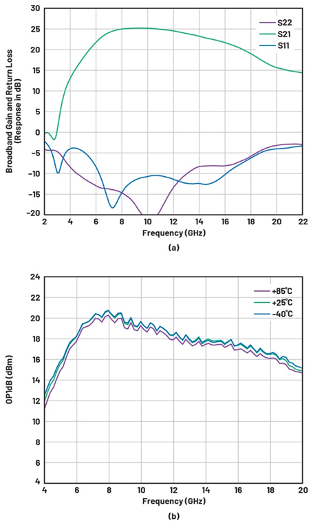
ADAR5000 (4:1 Wilkinson splitter/combiner) for beam distribution while the antenna FE options include the ADL8142 LNA designed for on-orbit applications in Ka band (23 GHz to 31 GHz). Packaged in a small, 2 mm × 2 mm LFCSP/QFN package, the ADL8142 is optimized for low noise figure (1.6 dB), high linearity (20 dBm OIP3), and high gain (27 dB) with power dissipation of only of only 50 mW from a voltage rail of only 1.5 V—see Figure 5 for details of the ADL8142 gain and noise figure. The ADL8142 is available in both COTS and commercial space versions. On the transmit side, devices such as the ADL8107 (8 GHz to 15 GHz, 28 dB gain, 19 dBm P1dB) or HMC498 (17 GHz to 24 GHz, 22 dB gain, 26 dBm P1dB) with their high gain and linearity can be used as element drivers. See Figure 6 for details of the ADL8107 gain and output P1dB.

Conclusion
Beamforming antennas are enabling the latest non-GEO satellite constellations to deliver on their promise of ubiquitous, flexible, and high bandwidth data communications. Designers of beamforming antennas can take advantage of ADI’s flexible offering of signal chain components from data converters through frequency converters and beamformers to FE components. The antenna FEs are critical in the overall signal chain as not only will they determine the noise performance of the system but also they have to conform to specific mechanical and power consumption constraints. ADI is developing a family of high performance devices such as the ADL8142 LNA that meets the unique requirements of on-orbit satcom.
About the Author
Jim Ryan is a product marketing manager with the Space Products Group based in Limerick, Ireland. He holds a B.Sc. (electronics) and M.Eng. (computer systems) from the University of Limerick as well as an MBA degree from the Open University (UK). He has worked with Analog Devices for over 30 years in roles including test engineering, product applications and marketing, and across a range of product types including precision converters, consumer A/V, and RF.


")


