


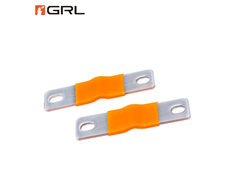
An electric-vehicle battery pack is not a static box of cells. During operation, it experiences vibration, shock, repeated heating and cooling, manufacturing tolerances and structural loads. At the same time, its high-voltage conductors must carry substantial current with low electrical loss and predictable temperature rise. GRL Copper is one manufacturer producing flexible copper connection components for EV and energy-storage applications.
That creates an interconnect challenge. A connection that is electrically efficient but mechanically too stiff can transfer stress into module, contactor, fuse or busbar terminals. A flexible connection that is poorly sized or badly terminated can create resistance and heat. Flexible copper links are useful because they allow designers to address both power transfer and mechanical compliance.
Battery Interconnects Carry Mechanical Loads
A busbar is not only a conductor. In a vehicle, it is also a mechanical component. If two terminals move relative to one another, a rigid conductor between them transmits force.
Some movement comes from road-induced vibration. Other movement develops as the battery heats under load and cools after the vehicle is parked. Pack structures, modules, copper conductors, plastics and insulating components do not all expand in the same way. Manufacturing tolerance adds another source of misalignment.
A well-designed EV battery soft connection introduces compliance into the high-current path. Instead of forcing all relative displacement into the terminals, the flexible section can accommodate controlled movement and reduce stress concentration when correctly sized and supported.
Why Stacked Copper Foil Works
One way to create flexibility is to replace one thick copper section with multiple thin layers. The total conductive cross-section can remain substantial, while each foil layer bends more easily than a solid bar of comparable overall thickness.
Flexible connectors of this type can use T2 copper foil with high copper content. In the linked product example, copper content is specified at no less than 99.95%, while individual foil thicknesses range from 0.03 mm to 0.50 mm, with 0.10 mm listed as a regular option.
An EV design should not be chosen from foil thickness alone. Current, temperature rise, dynamic movement, terminal geometry, joining process, packaging and fatigue requirements all matter.
The goal is to provide enough conductive cross-section for the electrical duty without making the connection unnecessarily stiff.
Resistance Sets the Thermal Baseline
Flexibility does not reduce the importance of resistance. Battery packs can carry high continuous and transient currents, so small increases in connection resistance can create localised heating.
Conductor loss follows P = I²R. As current rises, a marginal joint can become a significant thermal source.
Designers therefore need to consider more than the copper itself. The complete current path includes welded or pressed end sections, bolted interfaces, surface finishes, contact pressure and the terminals on connected components.
Temperature-rise testing is valuable because it assesses the assembled connection under realistic conditions. Electrical sizing and mechanical flexibility should therefore be developed together.
Vibration Turns Stiffness Into a Reliability Issue
EV components experience vibration over many operating cycles. If a stiff conductor bridges two points that move differently, repeated loading can be transferred to the conductor ends or terminal interfaces.
A flexible foil connector can lower the force required for a given displacement. That does not mean any soft conductor will automatically survive an automotive vibration profile. Foil geometry, unsupported length, bend radius, welded regions, terminal design and orientation all influence durability. Validation should reproduce the expected mechanical environment, with resistance checked before and after durability testing.
Thermal Cycling Creates Relative Movement
Battery temperature changes with ambient conditions, charging rate, cooling strategy and vehicle operation. These cycles make materials expand and contract. The important issue is the relative movement between the points connected by the conductor. A module terminal, high-voltage junction, PDU interface and pack structure may move by different amounts or in different directions.
Flexible connections can accommodate part of that mismatch without requiring terminals to act as springs. They may also help manage small dimensional differences during assembly. Engineers should still define a neutral installed position and an expected movement envelope. A connector that is already stretched tight or sharply folded at assembly has less freedom to accommodate later displacement.
Surface Finish Has a Specific Purpose
Copper provides excellent conductivity, but exposed copper surfaces can oxidise. Surface finish therefore matters at interfaces and in environments where moisture or contaminants may be present. Tin plating is one common option. It can provide a more oxidation-resistant surface and can improve solderability where soldering is part of the process. Nickel or silver may be selected for different temperature, corrosion or contact requirements.
Plating should be chosen for the joint environment and joining method rather than treated as a universal performance upgrade. The linked copper foil connections illustrate several available surface-treatment approaches, including bare copper, tin, nickel and silver finishes. The appropriate finish depends on the mating material, assembly process, environmental exposure and operating conditions.
Flexible Links Help With Packaging
Battery packs are tightly constrained mechanical systems. Cells, cooling plates, structural members, disconnects, contactors, fuses, sensing hardware and insulation all compete for space. A flexible copper link can bend or offset between terminals without requiring the same routing space as a heavy cable. Compared with a rigid bar, it can also tolerate small positional differences between components.
This is useful where the high-current path must fit around mechanical features. However, compactness should not be sacrificed in terms of clearance, creepage, insulation or serviceability. Some connectors may be physically able to fit into a narrow space but may be electrically unsafe due to improper insulation or electrical safety distances.
The Terminal Zones Matter
The flexible middle section gets most of the attention, but the terminal zones often determine whether the component performs reliably. Stacked copper foils can be consolidated or joined at their ends so that the flexible layers transition into a stable terminal area. Depending on the connector design, manufacturing methods may include welding or other joining processes suited to the copper thickness, geometry and required electrical performance.
Whatever process is used, engineers should evaluate resistance, mechanical strength, flatness, hole quality and consistency. The terminal interface must also match the fastener and mating surface. Contact area, torque strategy, hole position, hardware and plating compatibility should be specified as part of the system rather than left to the end of development.
What Engineers Should Specify
A useful flexible-connector specification may include:
- continuous and peak current;
- allowable temperature rise;
- copper grade and conductive cross-section;
- flexibility or foil construction;
- terminal and hole geometry;
- surface treatment and insulation;
- expected displacement and direction of movement;
- vibration and shock conditions;
- operating temperature range;
- resistance limits and validation methods.
Where the connection is safety-critical, production controls and traceability may also be required.
Conclusion
Flexible copper connections solve a specific EV battery-pack problem: they carry high current while allowing controlled movement between components. Their value is not simply that they bend. By reducing stiffness in selected parts of the current path, they can help engineers manage vibration, thermal expansion, dimensional tolerance and compact packaging without making terminals absorb every mechanical load.
The best results come from treating the connector as an electro-mechanical component. Cross-section, joint resistance, temperature rise, foil geometry, plating, terminal design, insulation and movement capability all need to be considered together. As EV battery packs become more power-dense and structurally integrated, that combined electrical and mechanical approach becomes increasingly important.