


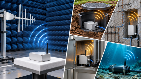
A product can pass a repeatable chamber test and still behave differently after installation. A wireless sensor placed under a metal lid, for example, may radiate less in one direction but couple energy into a cable or leak through a seam in another. The challenge is to preserve the rigor of laboratory measurements while evaluating the product as it will actually be used.
Why a standard setup matters
A semi-anechoic chamber or open-area test site controls the measurement geometry, ambient signals and reflections. Engineers can compare results against a defined method, investigate a failure and repeat the measurement after a design change. That is why standardized EMC testing remains the foundation of a compliance program, even for equipment destined for an unusual location.
The chamber does not, however, reproduce every installation. Buried meters, instruments inside reinforced concrete, electronics within metal cabinets and underwater systems interact with their surroundings. If installation conditions materially change emissions or immunity, engineers must account for them in the test plan rather than assuming a single chamber result describes every deployment.
The installation becomes part of the RF system
Soil, concrete and water can absorb and scatter RF energy. Their effect depends on frequency, moisture, conductivity, thickness and geometry; it cannot be represented by one universal attenuation figure. Metallic housings may shield the electronics while concentrating fields at apertures, gaskets, joints or cable exits. A connected cable can become the dominant radiating structure even when the enclosure appears well sealed.
These effects matter to both emissions and performance. A buried radio that radiates less into free space may also have less link margin. An enclosure that suppresses one emission path may create another through a bonded conduit. Practical RF testing therefore asks which antenna, cable, lid, power source and operating mode represent the product users will install.
| Installation | Likely electromagnetic effect | What to document |
| Buried pit | Attenuation and direction-dependent propagation | Depth, lid, enclosure and antenna position |
| Reinforced concrete | Loss and possible coupling to rebar | Material and representative geometry |
| Metal enclosure | Shielding with leakage at seams and cables | Apertures, bonding and cable routing |
| Underwater equipment | Strong, medium-dependent RF loss | Water conditions and intended communication path |
An FCC example with a narrow boundary
A useful example appears in the FCC’s Knowledge Database entry 139720. It asks whether a Part 15 water-meter transceiver intended only for an in-ground pit may be tested in a typical pit installation instead of on an open-area test site. The FCC answer is yes, but the resulting authorization is limited to the in-ground pit installation stated in the application and used for testing.
That distinction matters: the FCC example supports testing in a representative real installation; it is not a blanket permission to test an uninstalled unit in a chamber and then subtract assumed soil or enclosure losses. It also does not create a general exception for all underground or underwater products. The applicable rule, measurement method and authorization conditions still govern the particular device.
The European framework also depends on intended use
For apparatus within the scope of the EU EMC Directive 2014/30/EU, the electromagnetic compatibility assessment must address configurations the manufacturer identifies as representative of intended use. Documentation and installation instructions matter when correct assembly, connection or placement affects conformity.
A product that intentionally transmits or receives radio waves may instead fall under the Radio Equipment Directive 2014/53/EU, which includes electromagnetic compatibility among its essential requirements. Teams should identify the applicable framework before choosing standards or preparing a CE-marking file. That distinction is central to CE certification for connected equipment.
A test plan that connects the lab to the field
Start by defining the product boundary: its enclosure, antennas, cables, power supplies, accessories, operating modes and installation instructions. Record which variants will be sold and which locations the manufacturer permits. Then identify the applicable regulatory requirements and make baseline measurements under the prescribed, repeatable method.
Where the surroundings materially affect the result, add a documented representative-installation assessment or a justified engineering comparison. Change one relevant parameter at a time, such as pit lid material or cable routing, and measure both emissions and the radio’s ability to perform its intended function. Do not treat environmental attenuation as an automatic compliance margin: the same installation may introduce leakage through conductors or impair the desired signal.
Finally, make the evidence usable: document the configuration and photographs, explain the measurement method, distinguish measured results from estimates, and state authorization or installation limits in the product instructions and technical file.
The practical answer
Standardized laboratory tests provide reliable evidence; representative installation tests explain where that evidence applies. When the operating environment affects electromagnetic behavior, a defensible assessment connects the two through measured data, a clear technical rationale and installation instructions that match the product actually delivered.
About the author
Dr. Keyhan Sheshyekani is CEO of Stancer Testing-Lab and a Full Professor of Electrical Engineering at Polytechnique Montréal. He has more than 25 years of academic and industry experience in electrical engineering and electromagnetic compatibility.