

A New BOM, an Old Placement File: Can This Pilot Lot Be Released?
The assembly house has a new bill of materials (BOM), but its component placement list (CPL) came from the previous board release. A pilot lot is already on the bench. The new BOM specifies a different interface IC at U12. The old CPL still gives a position for U12, but cannot identify which IC was loaded. It also includes the underside connector J4, which the new BOM marks do-not-populate (DNP).
Neither conflict tells us, by itself, what was fitted. Before releasing the lot, the design owner and assembler need to establish the intended configuration, reconstruct the actual build and decide whether the available inspection and test evidence covers the differences. The next order needs a controlled package that cannot quietly reproduce the ambiguity.
The file that looks complete may still be wrong
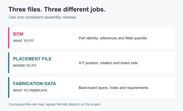
A BOM identifies the part and population status at each reference designator. The CPL gives positions, rotations and sides for placement; it does not prove which reel was loaded or which component ended up on the board. An unchanged coordinate for U12 says nothing about whether the replacement IC has the right pinout or polarity. Even matching package names are insufficient: compare the full manufacturer part numbers and data sheets with the footprint, assembly drawing and circuit requirements.
The export settings matter as well as the board revision. KiCad 9, for example, lets the exporter choose units and either the drill/place origin or the page origin. A bottom-layer option can negate X coordinates, and front and back positions can be exported together or separately. If a recipient assumes a different origin or bottom-side convention, apparently reasonable numbers can describe the wrong physical placement. Agree on the convention and compare a few known, asymmetric locations on both sides against the assembly drawing before accepting the machine setup. A numerical comparison without the convention is not enough.
KiCad can also exclude DNP footprints, non-SMD footprints or footprints with through-hole pads, depending on the export options. A missing connector from a placement file can therefore mean it is DNP, is to be assembled by another process, or was excluded in error. The CPL should not be treated as the complete population list. Agree which references the assembler expects in the file and keep the variant’s fit/DNP instruction in controlled assembly data.
Resolve the actual lot, not just the spreadsheets
First, identify the board revision, selected variant, released BOM and drawing, and each CPL and placement program actually issued to production. Record file identifiers or hashes where available; revisions need not have matching labels if their compatibility is explicitly approved. Preserve the old file and program. Overwriting them with corrected versions removes evidence of how the pilot was made.
Next, compare the designators and investigate mismatches. Use the table to record the evidence behind each disposition. Name the person responsible for clearing each open item:
| Check object | Common conflict | Basis for release |
| Board, BOM and CPL revisions | Old coordinates or package data were issued with a new BOM | Approved compatibility review against the actual board, assembly drawing and variant; corrected setup and inspection where affected |
| Fitted and DNP references | An optional position appears in the CPL or a fitted part is absent from it | Explicit fit/DNP list and inspection of affected positions; confirm whether absent parts require manual assembly |
| Part, footprint and orientation | Same reference and package name but changed IC or different rotation convention | Approved MPN-to-footprint and pin-one mapping; trace the loaded material and inspect the affected units using an agreed method |
| Substitution or repair | A different part was fitted or a board was reworked during the pilot | Written engineering disposition identifying the part, references and affected units, conditions and required verification |
| Test and repeat-build records | A generic power-on pass is used to close an unrelated discrepancy | Applicable inspection and test results tied to the lot, plus an authorised disposition and controlled next-build package |
A first-article review can detect a setup issue on the sample and features actually examined; it is not evidence that every board in the lot has the same configuration. Determine the affected population from setup records, material traceability, serial numbers and any changes made during the run. If that boundary cannot be established, agree an appropriate inspection or hold scope with the design owner. Do not infer a whole-lot pass from one board.
One mismatch, two possible dispositions
Illustrative example: Variant B specifies a new interface IC at U12 and leaves connector J4 unpopulated. The old CPL contains both designators. The assembler’s reel and setup records show that the new IC was loaded at U12; inspection against the drawing confirms the accessible orientation, and the agreed interface test passes on the affected boards. J4 is absent as required. Engineering may release the identified boards if the rest of the agreed acceptance criteria are met and the authorised owner records the decision. The old CPL’s extra J4 row remains a process issue to correct; its presence alone does not prove J4 was fitted.
Change one fact: the material record shows the old IC was loaded, and its acceptability for variant B has not been established. A passing power-on check does not resolve that conflict. Hold the affected units while engineering assesses the circuit and decides whether to replace the part and retest, reject the boards, or approve a bounded deviation. The decision must name the actual and intended parts, affected designators and serial numbers or lot, quantity, permitted use, required verification, approver and expiry or other limit. A deviation for this lot is not automatically permission to use the part in future builds.
Inspection and tests have different limits. Visual checks may show a marking or orientation when accessible; they cannot establish every electrical characteristic. A functional test establishes performance only under its stated inputs, loads and pass limits. If a board fails, retain the original result, investigation, any fixture correction or repair, and retest; a later pass alone does not explain the failure.
Make the next build reproducible
Close the pilot with a manifest linking the delivered lot or serial numbers to the actual board revision, BOM and variant, placement program, firmware and test procedure where applicable, material and inspection records, deviations, rework and final disposition. Decide which approved changes enter the next baseline and which concessions expire. Keep the pilot’s as-built history alongside the new release rather than silently replacing it.
For the next order, regenerate or correct the placement data from the controlled source, document the export settings and reconcile it with the approved BOM and drawing again. An enquiry to GREATPCB can include that manifest and ask for an engineering review of remaining discrepancies before production. The release decision then rests on a known configuration and recorded evidence, while the repeat order starts from a package another team can interpret.